Published: 1-February-2026Cisco dCloud Topology Builder User Guide
Save time developing and spend more time innovating for Exceptional Client Experiences (ECEs).
Streamline demo creation, by quickly turning your solution ideas into impactful, client-ready demonstrations you'll deliver with confidence.
Unlock the power and simplicity of Topology Builder for every demo.
Use this guide, videos, and ask for demo creation help in our Community Webex space—to build demos faster and deliver exceptional client experiences.
If you're new here...
There's a lot to discover in Topology Builder.
- For a quick overview, watch the Getting Started Guide video on the Videos page.
- To learn how to navigate Topology Builder, go to the Get Started menu and select the Explore UI Basics tab.
- For a quick refresher, go to the Configure a Topology and start with the General Settings page.
Instantly gain insights and get new ideas, as well as real-time support.
Boost Your Demos with These New Tools
Enhance your demos with the latest features and user guide content.
- Configure SaaS Integrations menu in this document: Go to the In this guide panel on the right.
- Launch Panel for scheduled content with IDAC-hosted recipes: Download and Watch Quick Video Demo to get started. Go to the Configure a Topology menu, then click the Push to dCloud tab.
- Export Diagrams to PDF, PNG, and JPG: Go to the Configure a Topology menu, then click the Diagram tab.
- Get Access
- Watch Training Videos
- Explore UI Basics
- About Licenses
Get Access
Getting access to the Topology Builder app is just a few clicks ahead!
The option you choose may depend on proximity.
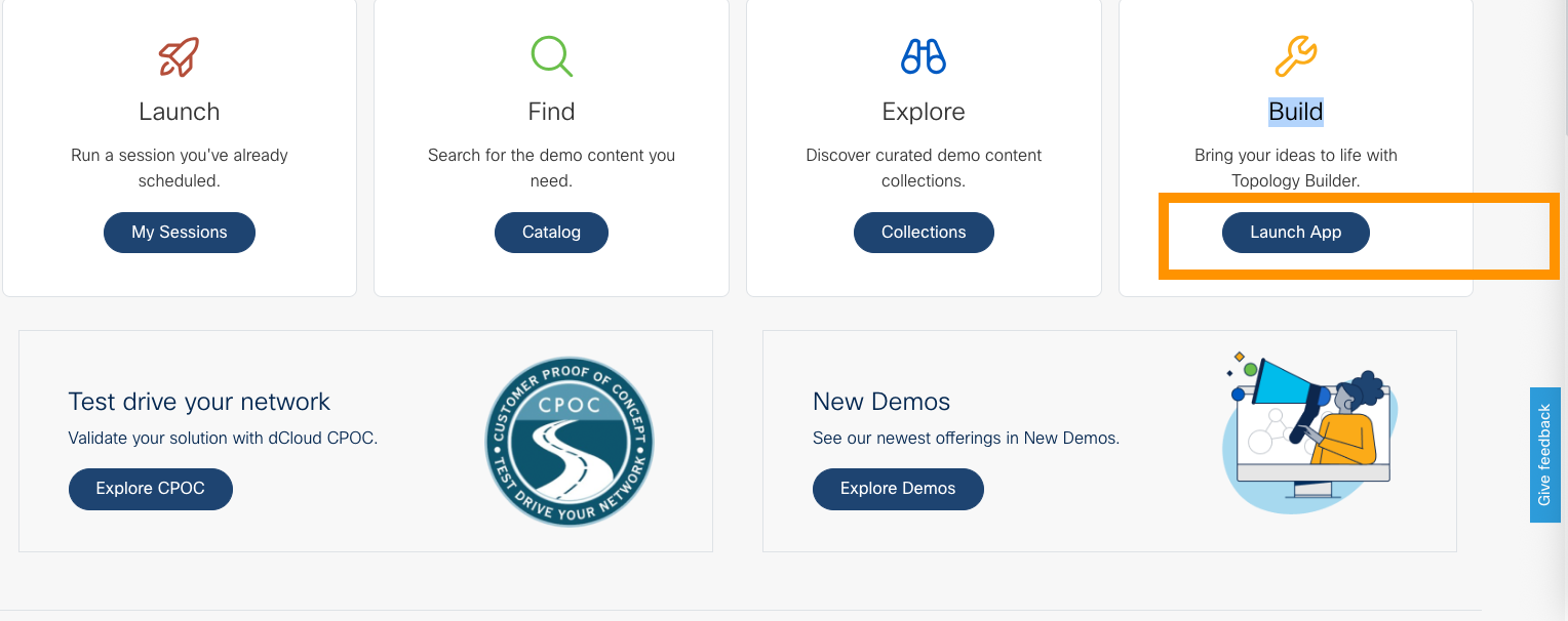
- Navigate to dCloud.cisco.com and click Launch App, below Build (the "wrench" icon) on the dCloud Home Page.
OR
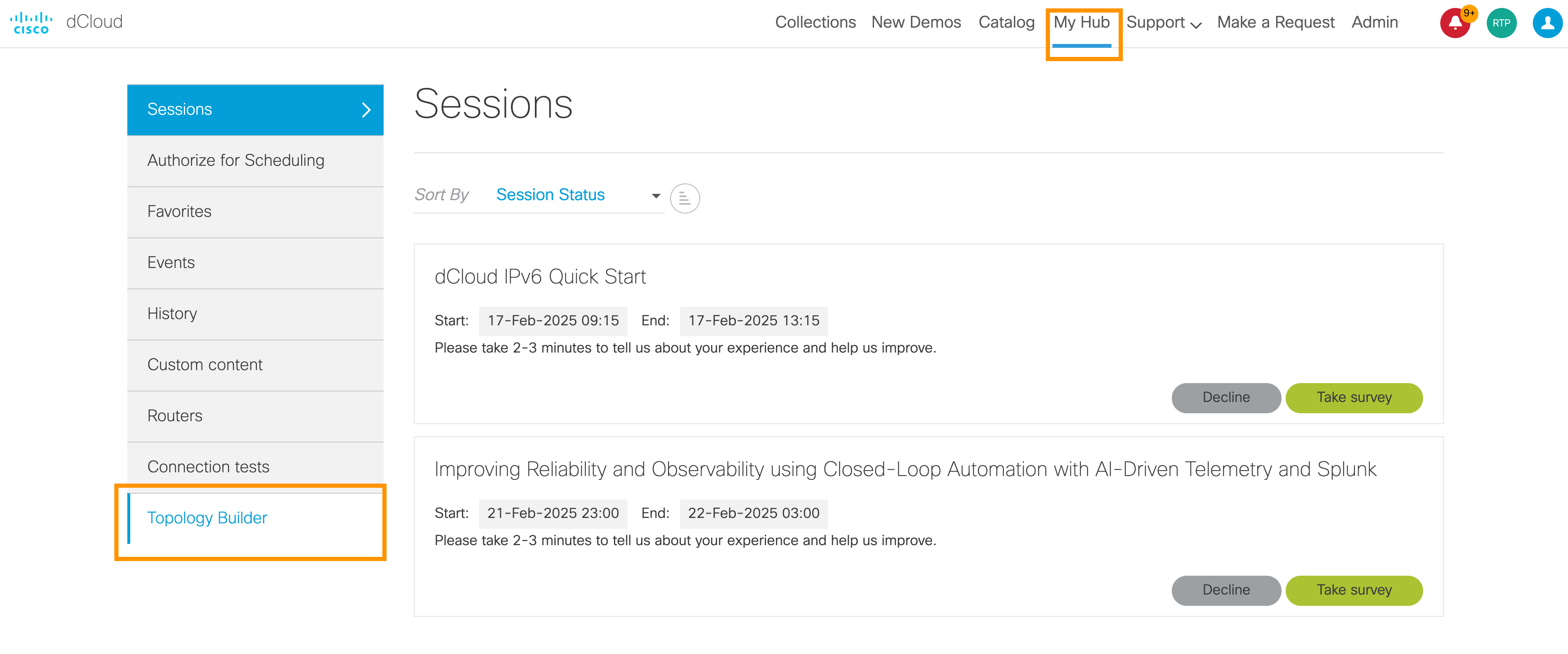
- At the top of any dCloud page, select the My Hub tab, and then click Topology Builder at the bottom of the left panel.
dCloud My Hub > Sessions Page
Bookmark the Topology Builder Home Page link and favorite the Topology Builder Community Webex space where a large forum of diverse teams ask for demo creation help. As you begin using Topology Builder and the Community space, you will see clear benefits that lead to excellent customer business outcomes.
How to access: Partners
Log in with your Partner email.
If you are a Partner not yet associated to their account/company, you can do that through this link: https://pss.cloudapps.cisco.com/WWChannels/GETLOG/welcome.do
How to authorize dCloud access for a customer
Go to My Hub and add the email of the user you want to add.
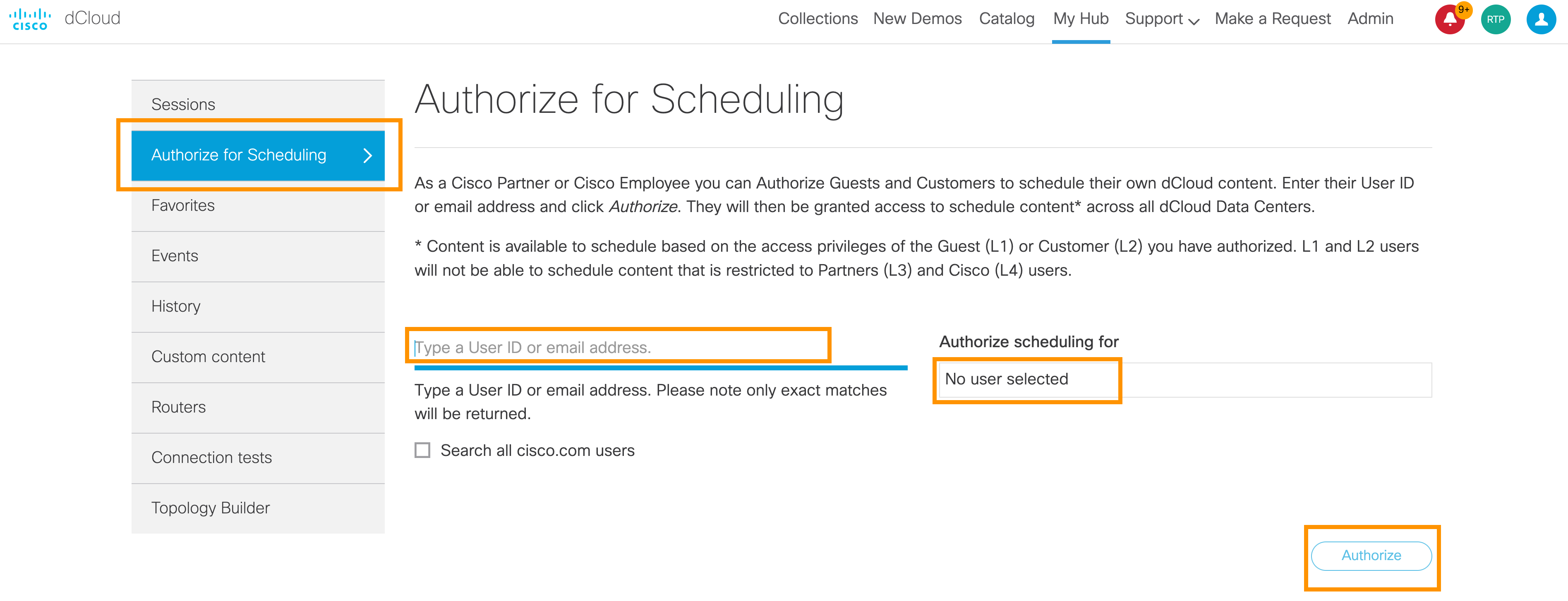
Note: The user will only show if they have already logged in to the DC.
Need Help accessing Topology Builder?
- Click https://tb.ciscodcloud.com/, and then click Request.
- If you have questions, email dcloud-support@cisco.com.
Licensing for Topology Builder is internally managed by the dCloud team. It is not related to software or hardware licensing but used to control the volume of sessions running on Topology Builder. For more info, select the "About Licenses" tab above.
Watch Training Videos
A great way to get to know Topology Builder and learn how to use it is to watch the growing list of video tutorials we offer.
- On the Home page, click the Play button to see a variety of short videos on building topologies.
These short videos are an excellent way to learn more about creating and deploying topologies. For example, you can learn how to create a topology, run it in dCloud, configure sharing and remote access, share a topology, and more.
Recommended: Click the Getting Started Guide Play button at the top, for a quick, guided tour of the application.

What's Next
On the Get Started menu, click Explore UI Basics, to become familiar with Topology Builder navigation and preferences you can set.
Explore UI Basics
As you get started in Topology Builder, it is good to review the user interface (UI) basics.
- Go to the Home page
From the Home page, you can launch My Topologies, Documentation, Template Manager, Videos, or Request a Feature.
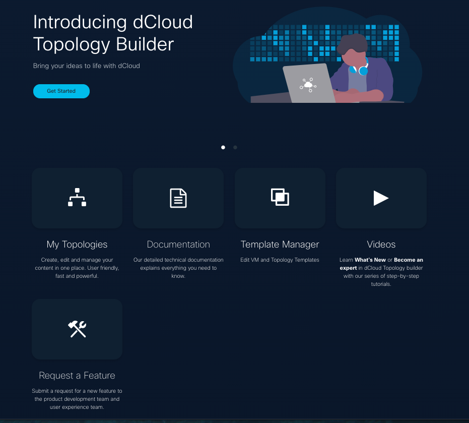
If you click Get Started on the Home page, you will launch the My Topologies page.
At top left of any Topology Builder page, click the Cisco dCloud Topology Builder to go to the Home page.

At top right on any Topology Builder page, click Home to return to the main window.

- Go to My Topologies page

You can always go Home and click Get Started to open My Topologies, as well.
- Toggle UI Themes: Dark Mode | Light Mode

Light Mode

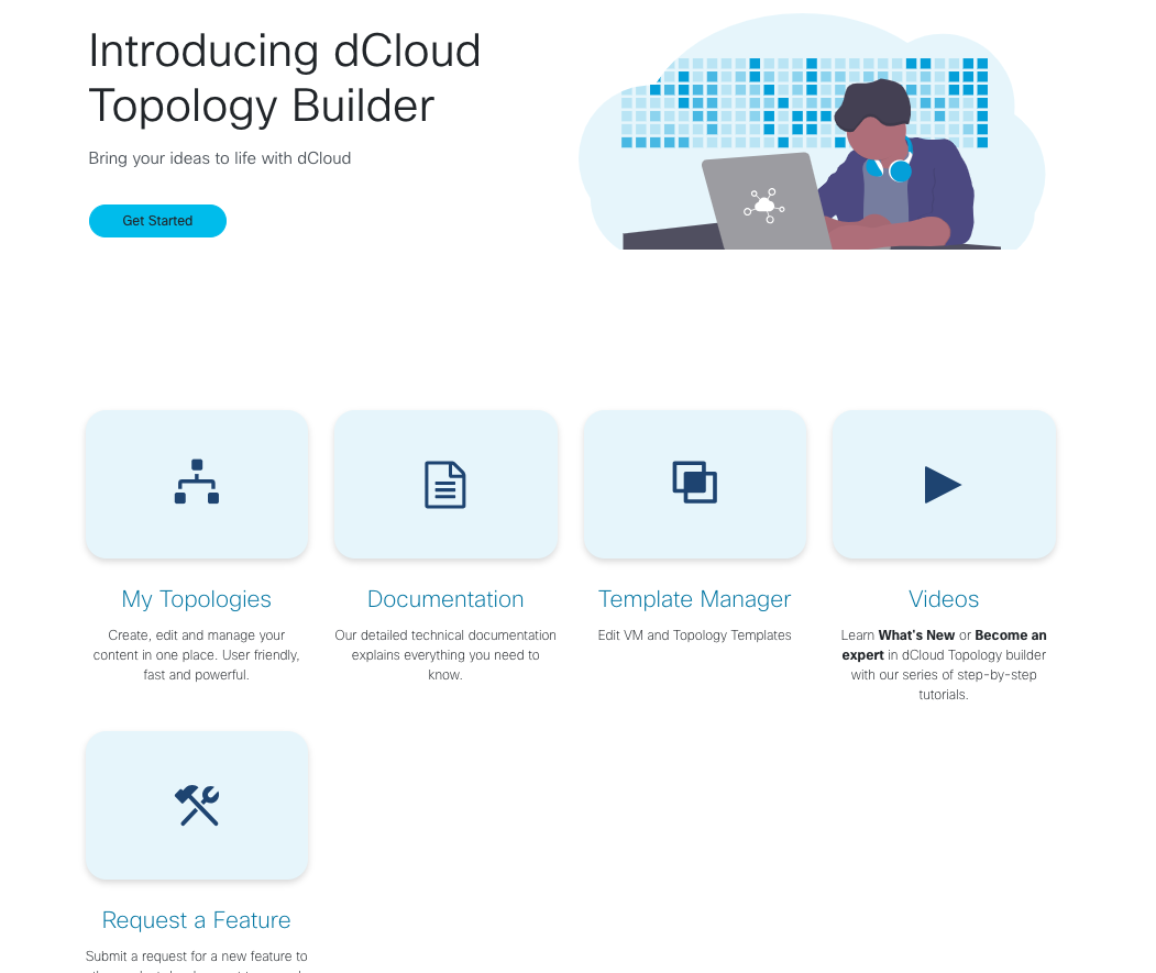
Dark Mode


- Toggle Topology Views: List View | Detailed View

Click the image on the right, to toggle to Detailed View on the My Topologies page.
My Topologies Detailed View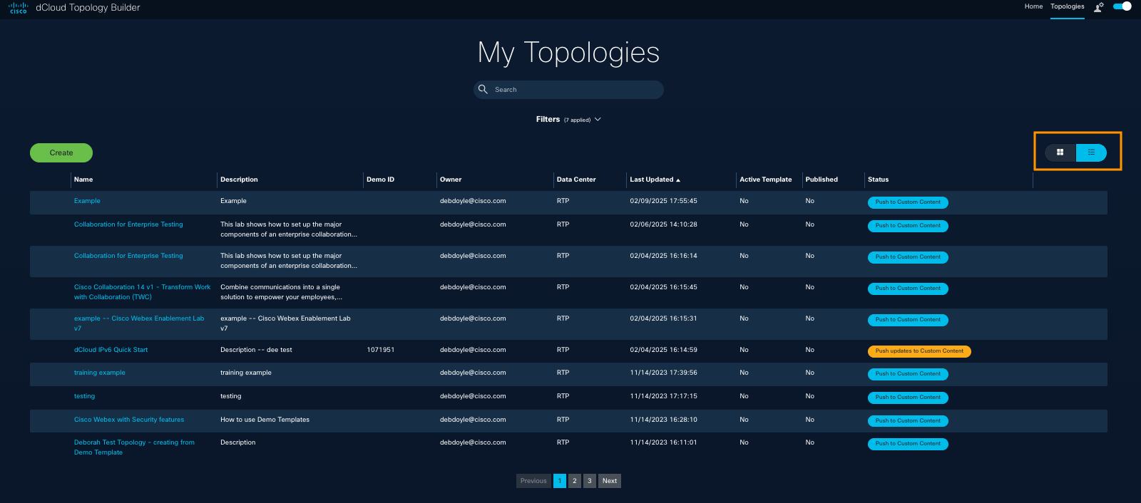
When you have created 8 topologies, your view will auto-display in Detailed View, at the beginning of each new session.
Click the image on the left, to toggle to List View on the My Topologies page.

My Topologies List View
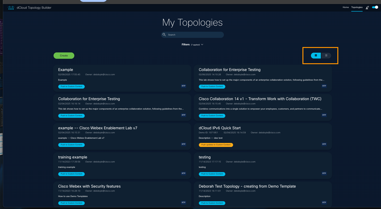
When you have created eight topologies, your view will auto-display in Detailed View, at the beginning of each new session.
- Search

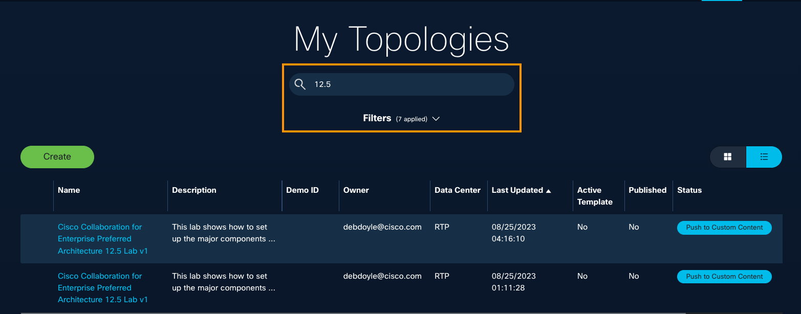
On the My Topologies page, click within the Search field, and enter a topology name or keyword in its description, to see the list of matching topologies.
Tip: If a version number might be part of the topology name or description, enter it (for example, enter "12.5") to see the list of results.
- Filter Search Results
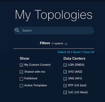
1. On the My Topologies page, under the Search field, click the arrow to expand Filters.
2. Select Filter options to improve the results shown, by Content type and/or Data Center location.
- View / Delete Personal Preferences
You can quickly see the preferences you have set and/or delete all preference at once.You cannot change individual preferences here. To do that, scroll up to find Toggle UI Themes; Filters; and Topologies View.
- Select the Person icon at top right.

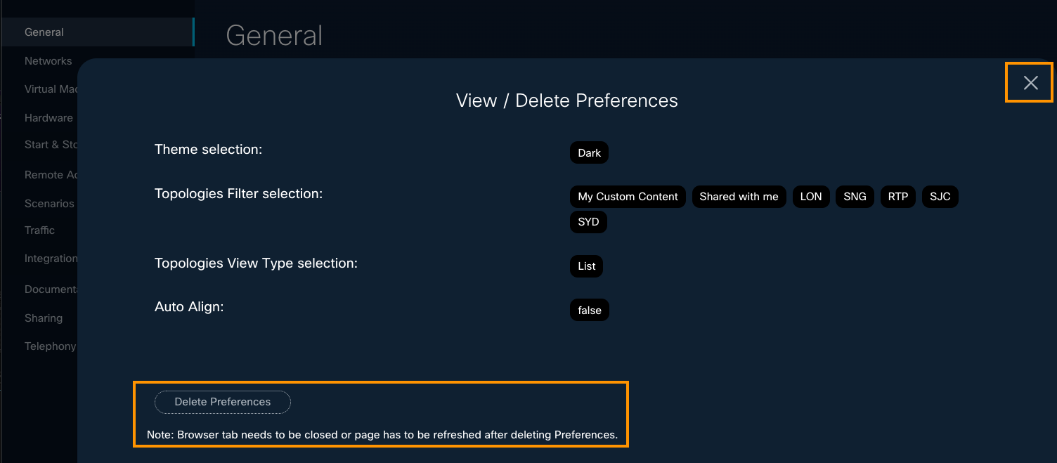
- On your View / Delete Preferences page, review your current UI preferences.
- To keep your personal preferences in tact, click the X at top right to close the pop-up page.
- To simultaenously remove all of your preferences, click Delete Preferences at bottom.
- If you delete all your personal preferences, you can scroll up or search within this guide, to learn how to add your preferences in this UI Basics section: Toggle UI Themes: Dark | Light; Filters; and/or List | Detailed View.
- Get Support
At bottom right of any page, click the information icon, to see three choices you can click to get support.
Demo Creation Help takes you to the Topology Builder Community Webex space where you can ask questions and get expert advice. This is quite popular and effective, as you will see.
dCloud Support opens the Support page where you can open a ticket; click Help to check online help topics; click Tickets to see your open tickets and status; and click Feedback to tell us about your experience.User Guide opens the guide you are reading now.
- Give Feedback
Share your Feedback about Topology Builder in the TB app's page footer, or click Give Feedback on the right of pages in this guide.
* At the bottom of any TB page, click Feedback in the footer.

* On the right of any TB User Guide page, click the small, vertical Give Feedback banner.

Great job!
You have learned basic navigation and tips to make navigating your journey simple and effective.
What's Next
Now, you are ready to create your first topology. Let's look at how to do that from scratch and from an existing demo template. You will start with the concepts and basic tasks, and then get into the flow.
On the Get Started menu, click Create a Topology.

- Prepare
- Create from Blank
- Create from Template
- Edit | Delete
- Copy | Clone
- Share
- What's New?
About dCloud Topologies
The dCloud Topology Builder application is designed to help you—whether you’re a Developer, Solutions Engineer (SE), or another Cisco expert—efficiently transform world-class solution ideas into compelling demonstrations.
Start by building a topology that efficiently designs the best Cisco solution for your customers—delivering insight, confidence, and enabling sales.
Articulate the story > Build the Cisco solution > Empower Cisco sellers with great content > Enable sales > Customers win, and Cisco wins!
Topology Builder empowers you to quickly build, customize, and reuse network topologies to support your sales objectives. Designed for developers, Solutions Engineers (SEs), and other technical users, Topology Builder streamlines your workflow and enhances productivity.
As you begin using Topology Builder, you will see clear benefits that lead to excellent Business Outcomes for your customers.
- Build topologies faster.
- Discover ways to customize them to configure solutions that deliver high customer value.
- Reuse parts of your current topologies to construct new ones for other accounts.
- Use Topology Diagrams in your sales pitch to help customers "see the WHY" behind the Cisco solution.
To learn the fundamentals of a dCloud topology, you will explore two methods - creating from scratch with a Blank Template or from a Demo Template as your foundation.
Create from Blank
Create your topology content from scratch, with no prebuilt templates. Keep in mind that you can select prebuilt virtual machines later, when you edit your topology's configuration.
Create from (Demo) Template
Create content from a prebuilt demo template created by the dCloud developer team. This may be an existing demonstration or lab in the dCloud Catalog.
Create from Import
Available only to the dCloud Development team, this option is used to import Topology Builder version 2 content into version 3 for editing.
Note for Template Managers: If you are unable to locate a new VM or Demo Template, please raise the topic in our Community Webex space.
Before you create your first topology...
Before you create your first topology in the Topology Builder app, it is recommended to familiarize yourself with the application to set your expectations and navigate efficiently:
- On the Home page, select Videos and click the Getting Started Guide video at top of the page. This video provides a friendly tour of the app.

- It is also helpful to review some navigation tips. Scroll up to the Get Started section, select the Explore UI Basics tab, and spend about 2 minutes on a quick review to understand the user interface and basic operations.
Ready to get started? Explore Topology Builder and unlock new ways to showcase Cisco's value!
Create Your First Topology
On the My Topologies page, you will create your first topology, which you can do in a couple of ways, depending upon what you want to build and/or leverage with prebuilt demo templates. It's a good idea to try both methods, in the order in which you're comfortable, as you get familiar with the TB app and how to get the most out of it.

First, you will determine whether to start from scratch (Blank) or start with a prebuilt dCloud demo topology (Template).
As you create your topology, observe where you are in the process at top of the My Topologies page.

The simplest way to create a topology is to use a prebuilt template that was created by the dCloud developer team, and add/ remove components to fit your use case. This may be an existing demonstration or lab in the dCloud Catalog.
Create from Blank: Prerequisites
To get started with Topology Builder and learn to create a topology from scratch, following 3 Setup Steps:
1—Create your project folder.
2—Create a topologyname.virl file.
3—Place nodes and create connections to design your topology.
1. Create a Topology Project Folder.
Before creating a topology, ensure you have a topology project folder. You can create a project folder via:
- Menu Bar: File > New > Other > Topology Project
- Projects View: Right-click > New > Topology Project
- Toolbar: Click the New Topology Project icon
- Enter a project name, select the save location, then click Finish.
2. Create a Topology File.
Within the project folder, create a topology file with a .virl extension using one of these methods:
- Menu Bar: Select a project folder, enter filename ending with .virl, and click Finish
- Projects View: Right-click > New > Topology, select project folder, enter filename, click Finish
- Toolbar: Click New Topology File icon, select project folder, enter filename, click Finish
3. Place Nodes on the Canvas and Create Interfaces and Connections: Design a Topology Overview.
- Open the topology file to access the canvas in the Topology Editor.
- From the Palette view, select node types under the Nodes heading and click the canvas to place them.
Tip: You can drag nodes to reposition them and use selection tools (Shift-click, Ctrl/Cmd-click) and menu options (Edit > Grid > Distribute Nodes) to arrange them. - Create Connections and Interfaces: After placing nodes, proceed to create connections and interfaces between them to build your network topology.
- Add Prebuilt VMs as Needed: You can add prebuilt virtual machines later to enhance your topology.
This process enables you to "Create from Blank," meeting basic requirements and enabling you to showcase Cisco’s value effectively through network simulations and demonstrations.
For detailed guidance, refer to the Cisco Modeling Labs Corporate Edition User Guide.
Create from Blank—7 Main Steps
With Topology Builder, you can quickly create a topology without a prebuilt template, to build a new dCloud demo from scratch.
Keep in mind that you can select prebuilt virtual machines later, as you edit your topology configuration.
To create a topology from scratch, follow these steps.
- On the Home page, click Get Started.

Or, at top right of any page, click Topologies.
- On the My Topologies page, click Create.

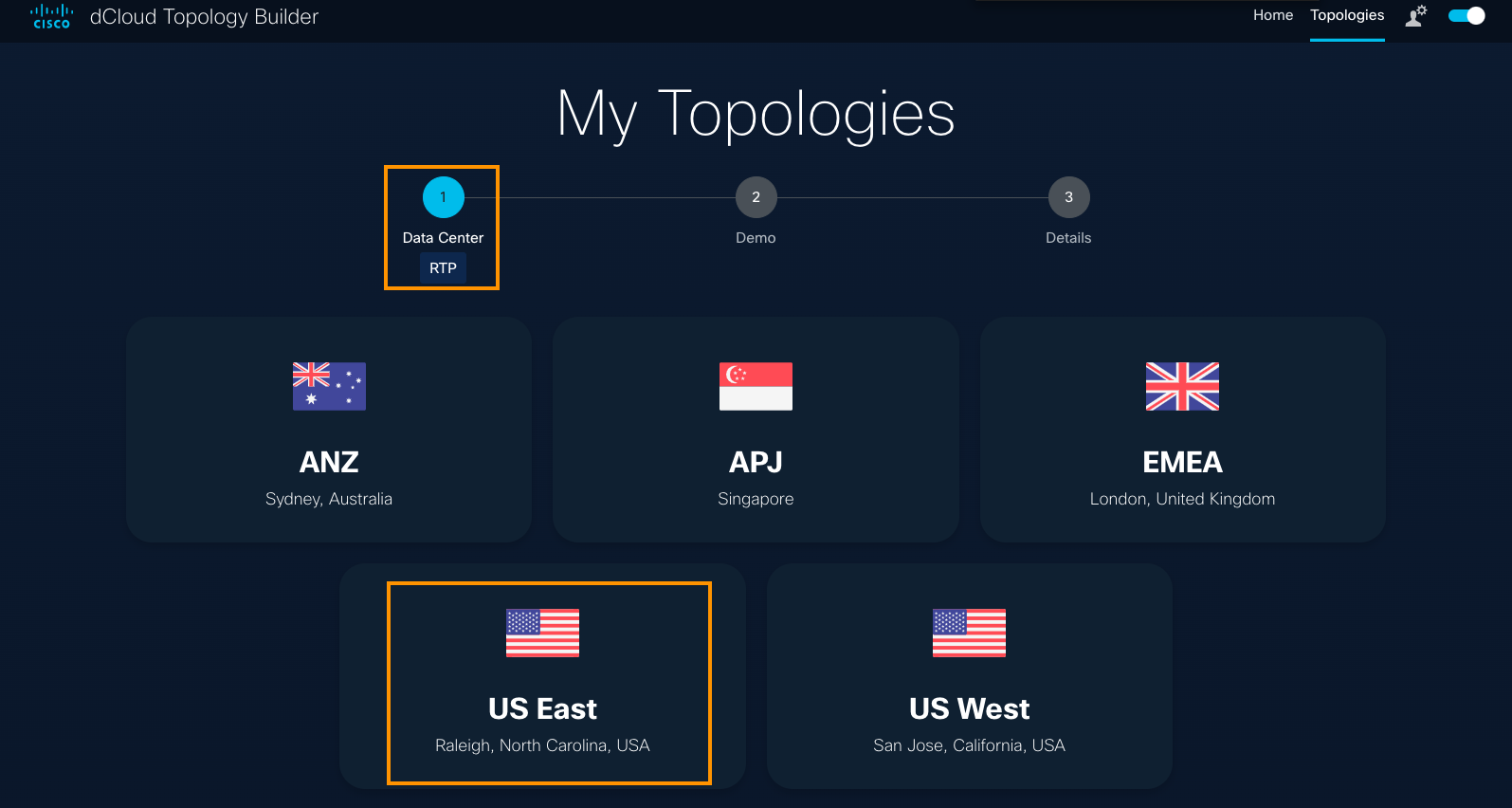
- Select the Data Center where you want to publish the content.
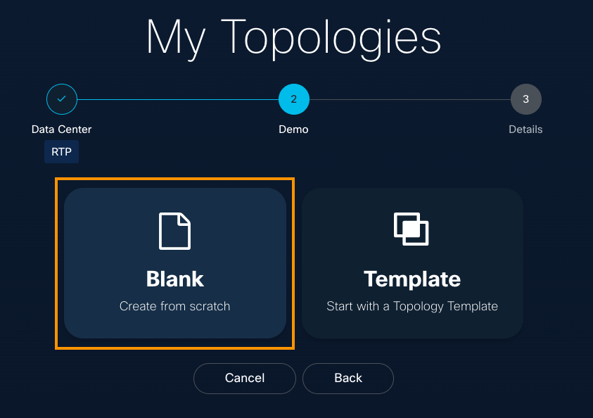
- Select Blank.
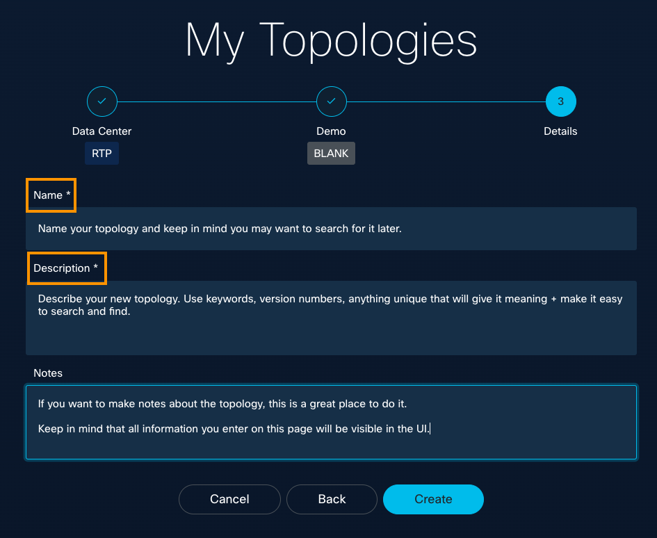
- Add the details: Give your new topology a Name and Description (required), and add any helpful Notes on this page. All information you enter here will display in the UI.
- On the General configuration page, you can edit the Name, Description, and Notes. If you do make edits, click Save.
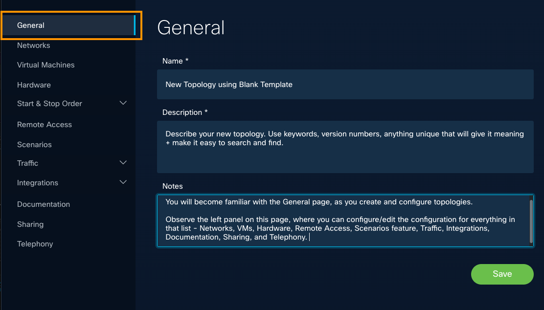
- From here, you can select options on the left panel to continue editing your topology's configuration details.
For configuration instructions, scroll down this page to the Configure a Topology menu.
Good job!
You've learned how to create a topology from a blank template and that you can go back to make further edits and configurations later.
What's Next
Now, Scroll up to the Create a Topology menu and select the Create from Template tab, to learn about the basic topology requirements and how to build a topology from a prebuilt demo template. You can customize it later, as you like.
Create from Template
You can create content from a prebuilt template developed by the dCloud team. These templates may be existing demonstrations or labs available in the dCloud Catalog. Using a template is a popular way to start with a configuration similar to what you want to develop.
For a guided tour, go to Home > Videos and watch the Create from Template tutorial.
To create a topology from a demo template, follow these steps.
- On the Home page, click Get Started.
Or, at top right of any page, click Topologies.
- On the My Topologies page, click Create.

- Select the Data Center where you want to publish the content.

- Select Template.
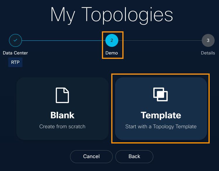
- Search for a template or browse the Template list.
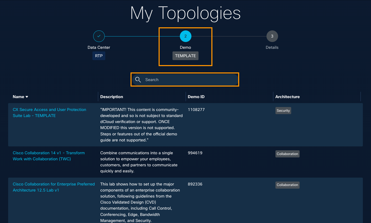
- For example, scroll down to find the template used for this demo:
Cisco ISA3000 with FTD - FMC version - Lab v3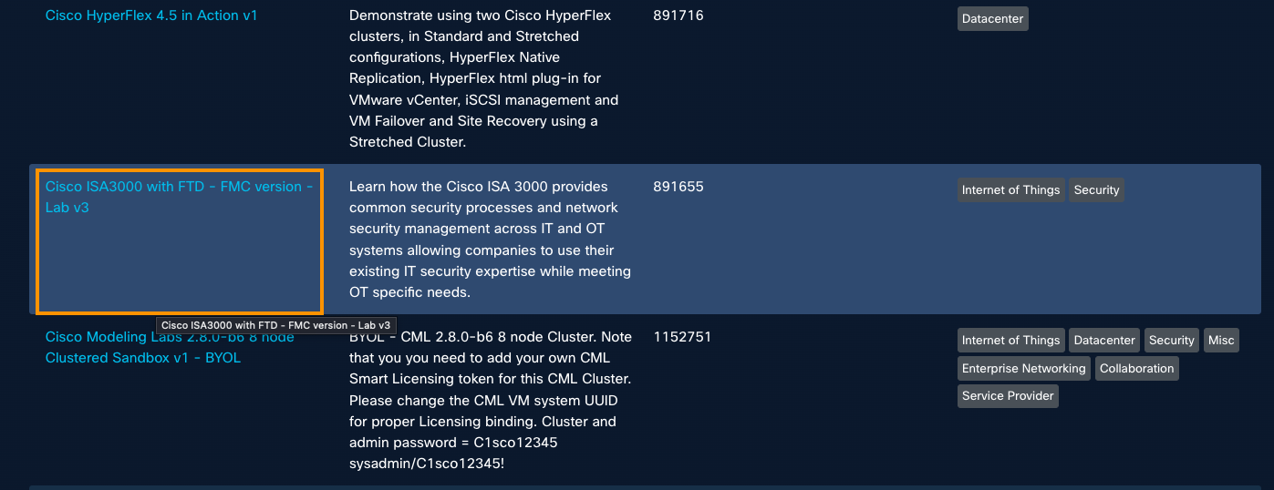
Click the template name to view its Name and Description.
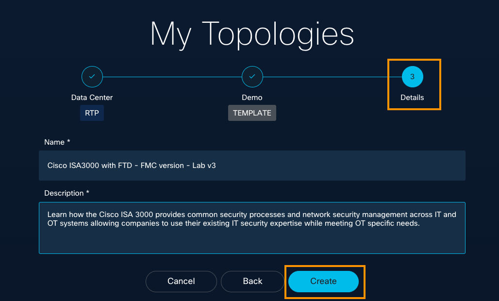
- Change the Name and/or Description as needed, then click Create.
- On the General tab, add a meaningful note, then click Save.
To continue editing the configuration, use the options on the left panel.
Great job!
You have learned the basics of creating a topology from a Blank template or template that is based on a proven dCloud demo. Nice work.
You've got a template with which you can develop your dCloud instant demo, lab, scheduled demo, or sandbox exceptional client demo experience.

To dive deeper into configuration now, scroll down a bit to the Configure a Topology menu.
Otherwise, continue with the Create a Topology menu, and explore how to edit, clone, and share your topology.
Edit a Topology
You may want to edit a topology whether or not it has been saved to Custom Content on the dCloud platform. For example, you can edit an existing topology for a different customer or solution and save it with a new name, or further customize a current topology.
Topology Builder enables full customization, and you can access all topologies you create using Topology Builder on your My Topologies page.
To edit your topology, follow these steps:
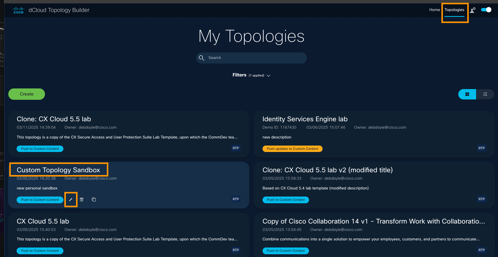
- At top right of a page, click Topologies.
- On the My Topologies page, click the Pencil icon below the topology you want to edit.
→ If the Pencil icon is not visible, click any blank space on the page and hover over the topology name again.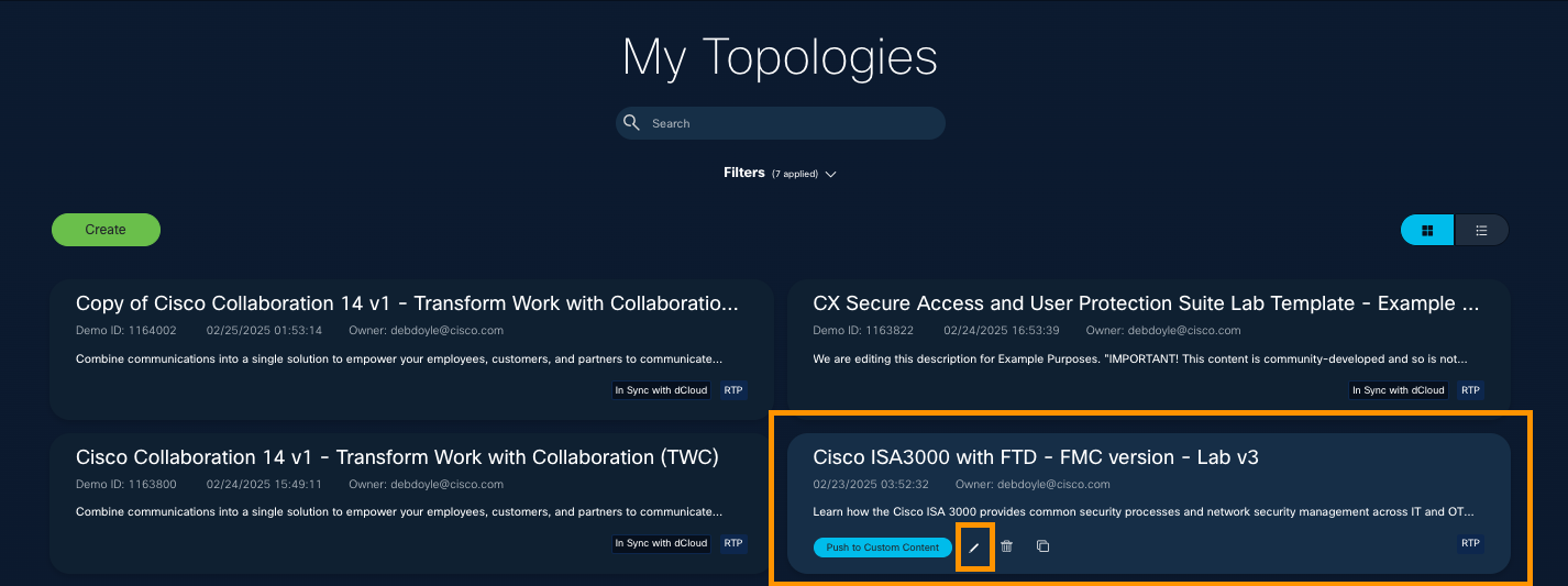
- On the General configuration page, you can edit the topology's name, description, add any notes. You can check the Enable guest access checkbox.
- Use the left-panel menu to edit the topology's configuration.
- If you make any edits, click Save.
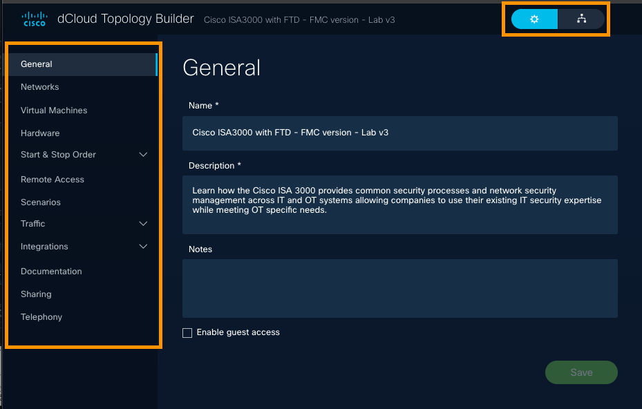
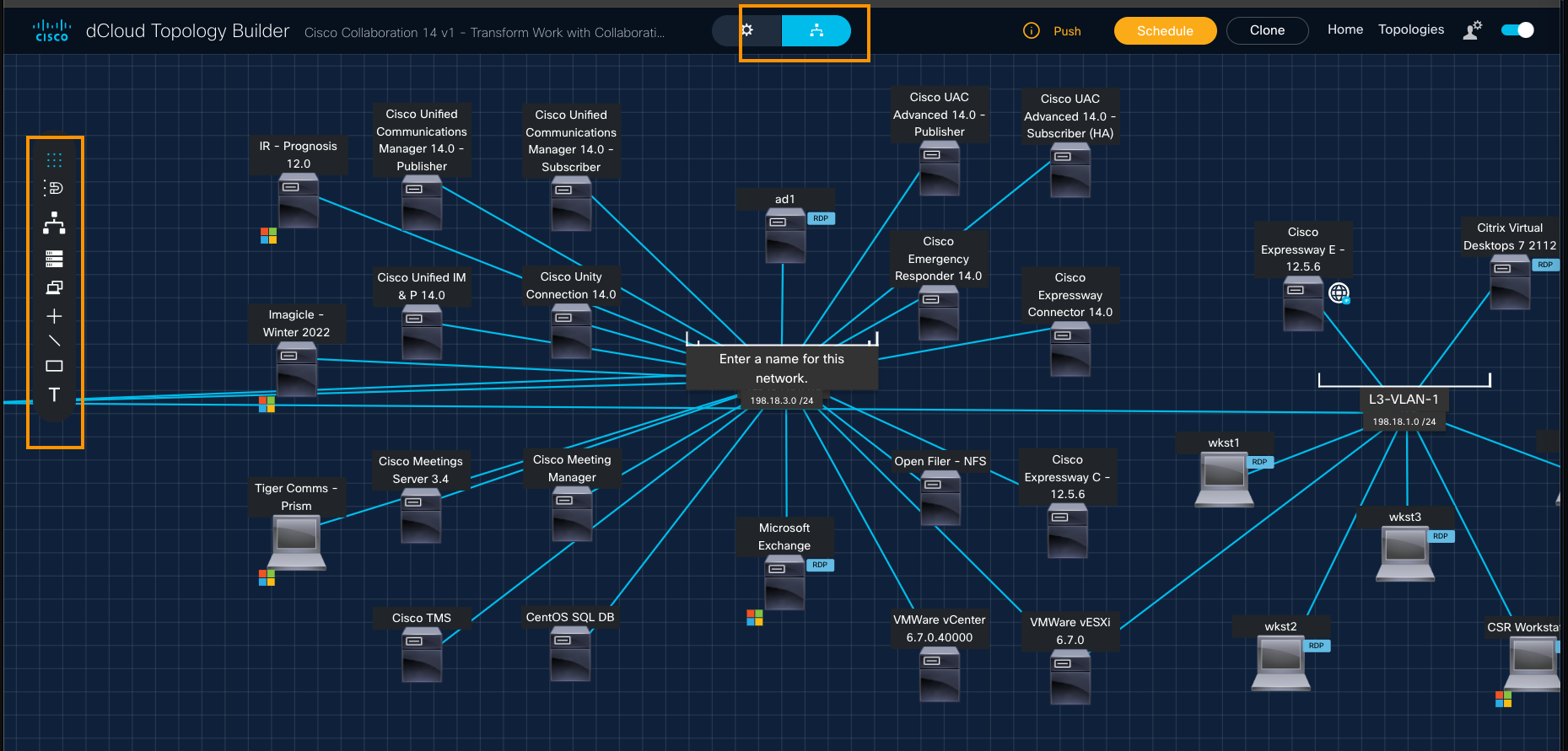
At the top, observe the toggle buttons where the gear icon is selected by default.
If you toggle to the Diagram View on the right, your topology’s diagram will display.

You have various options to modify the look and feel of your diagram. Refer to the Configure a Topology menu in this guide and select the Diagram tab to xxdd
Delete a Topology
You can access all topologies you create using Topology Builder on your My Topologies page.
If you choose to delete a topology, it will be deleted from Topology Builder, so consider carefully whether you want it deleted from the system.
If you delete a topology that has been saved as Custom Content in dCloud, it will no longer be available.
To delete a topology, follow these steps.
- At top right of a page, click Topologies.
- On the My Topologies page, click the Trash icon below the topology you want to edit.
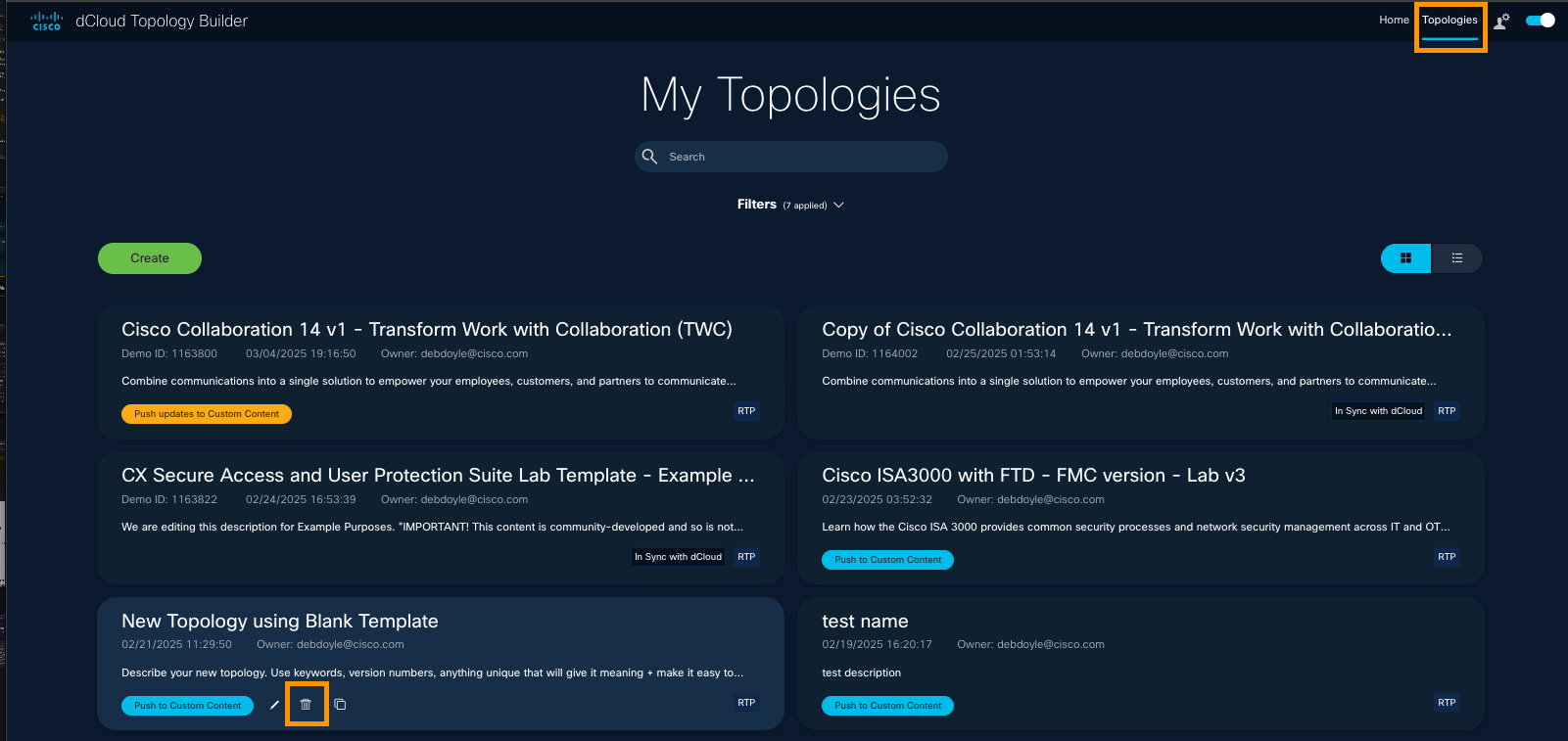
If you do not see the Trash icon, click any blank space on the page, and hover over the topology name again.
When the Confirm Delete message appears, click Delete if you are sure. This will delete the selected topology from the system. Therefore, be sure you do not want to leverage it, customize it, and rename it before you click Delete.
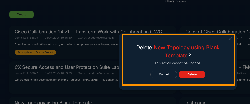
Copy or Clone a Topology
Imagine that you are happy with a topology you created and you want a new instance of it that you can build upon, edit, and reconfigure for a new solution.
Or, maybe you would like to archive a topology to reference or use later, so you'd like to make a copy of it, make a note about it on the General page, and change the name to begin with "Archive." How and when you make copies of topologies will depend upon your dCloud content development requirements and process.
Whether your content exists in dCloud, you can copy or clone your topology.
When you copy your topology, you must make at least one edit in one field on the General page: Name, Description, Notes.
When you clone your topology, you can modify the Name and/or Description, but you can click Create without having done so.
Copy a Topology
- At top right of a page, click Topologies.
Here is where you access all topologies you have created, copied, or cloned.
- On the My Topologies page, click the Copy icon below the topology you want to edit.
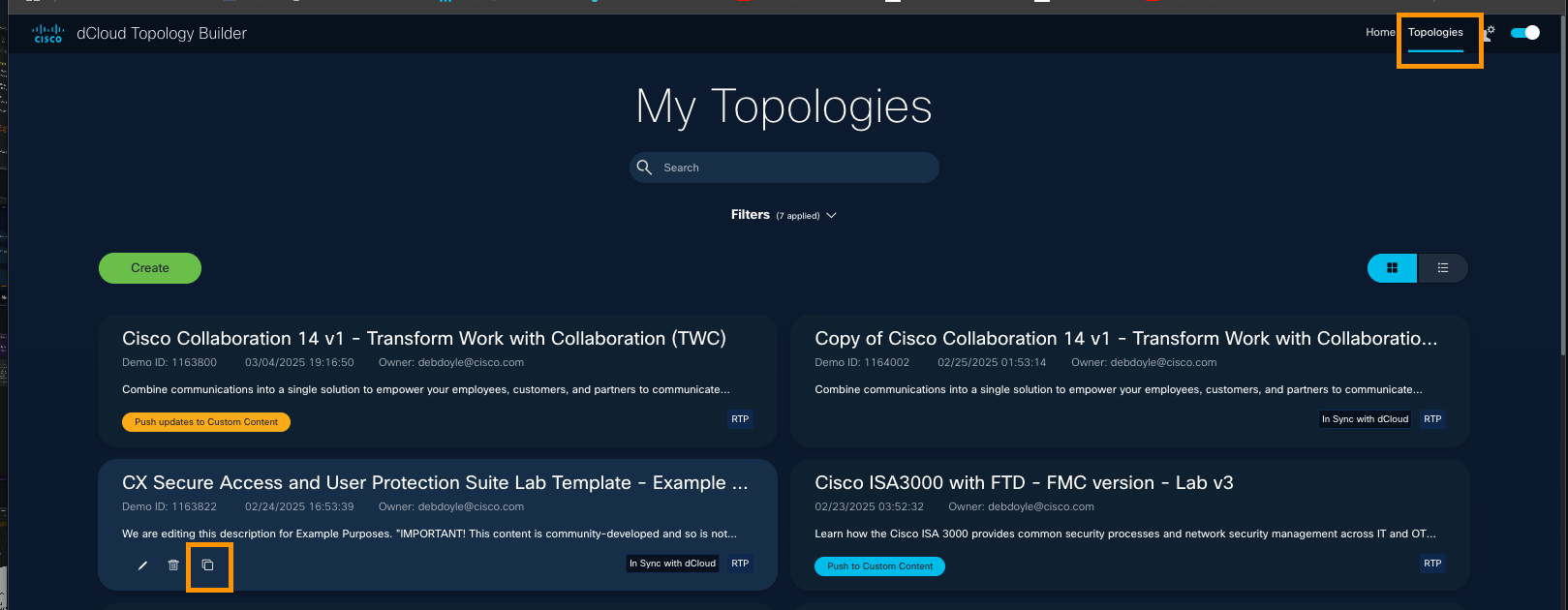
If you do not see the Copy icon, click any blank space on the page, and hover over the topology name again.
- Before you can save this Copy, you must make a change to at least one of the three fields that displays: Name, Description, and/or Notes.
While you can modify these further on the General page at any point, it is best practice to add a useful Name and Description now, because clarity of the content's goal will help later. Consider writing a meaningful Description, like "Cloned from [original-topology-name] to create [new-lab-name]."
- Click Save to add this new copy of a current topology to the My Topologies list.
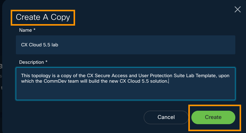
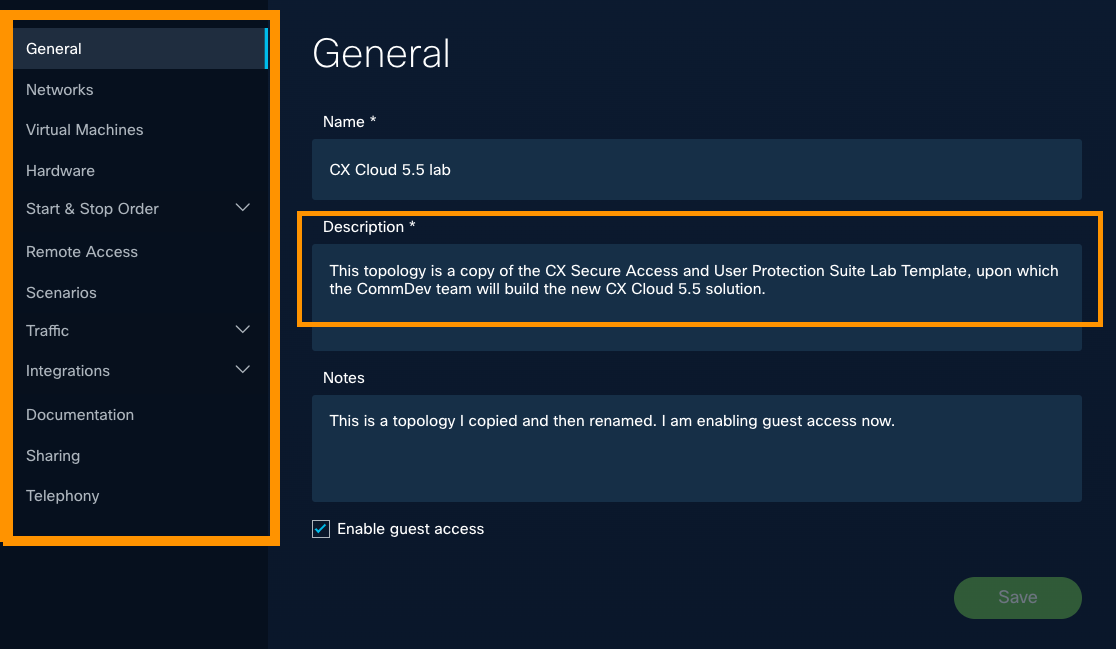
- Observe that when you have clicked Create, the General configuration page for the new copy of the topology displays.
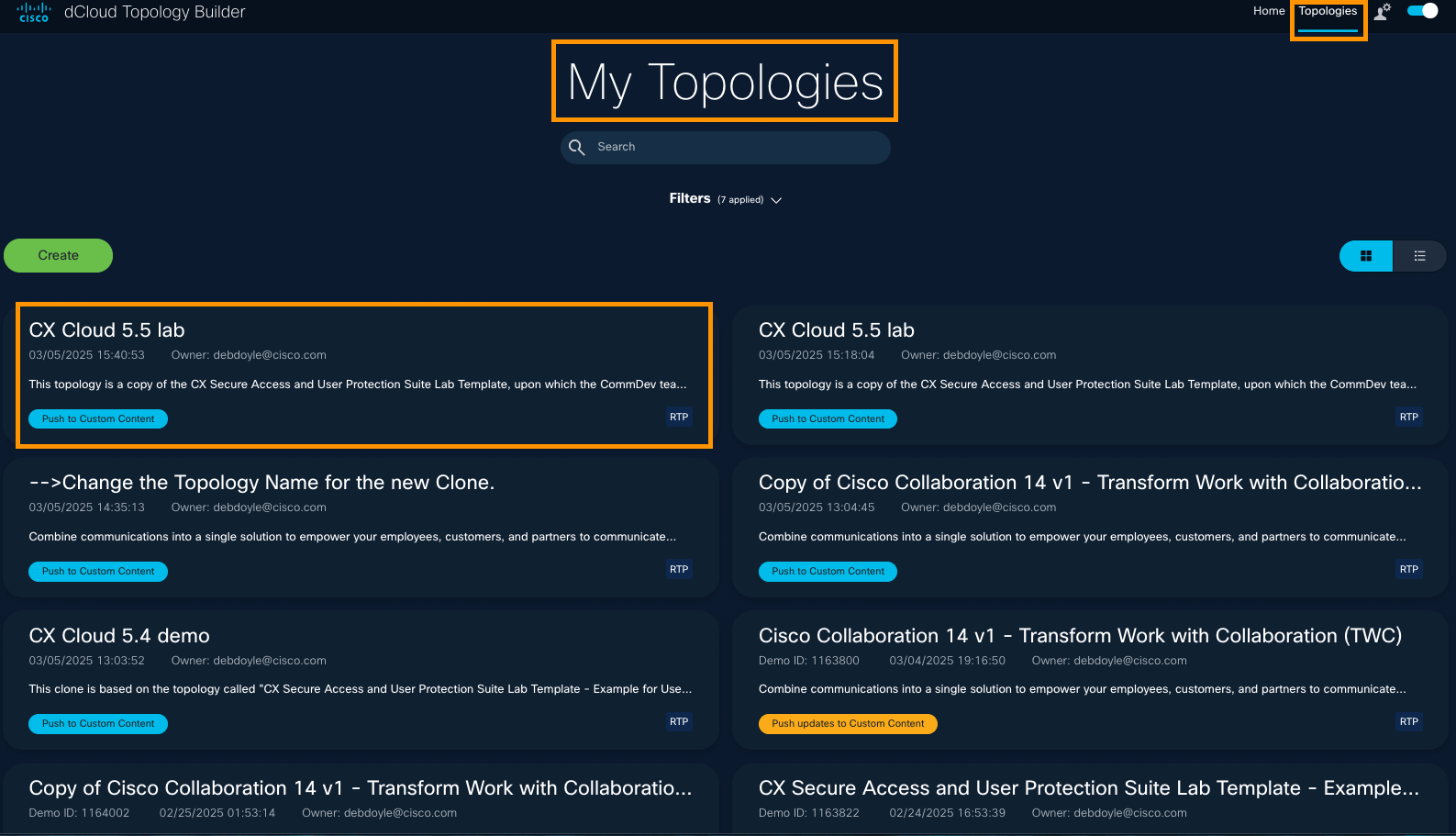
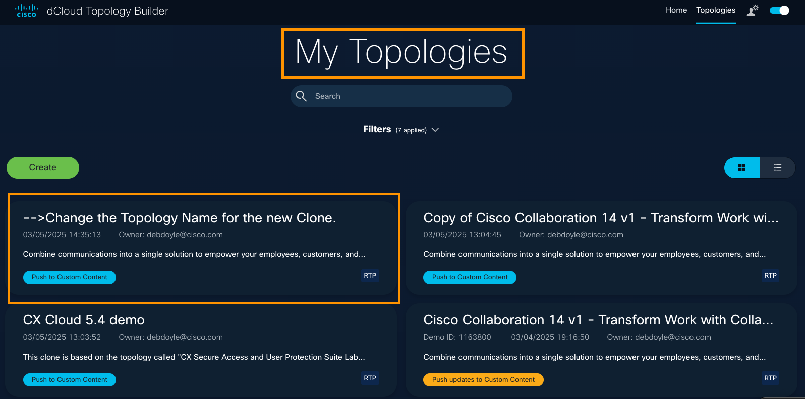
The title and description for your new topology (clone) will now display on your My Topologies page.
Clone a Topology
Imagine that you are happy with a topology you created and you want a new instance of it that you can build upon, edit, and reconfigure for a new solution. You may want to clone an existing topology, whether it has or has not been saved to Custom Content on the dCloud platform.
You might choose to copy or clone a current topology, save it with a new Name, Description, and add a helpful note like "The base of this topology comes from the Collaboration 12.6.2 Sandbox."
You can access all topologies you have created on your My Topologies page.
To clone your topology, follow these steps.
- At top right of a page, click Topologies to open the My Topologies page.
Here is where you will access all topologies you create, copy, or clone.
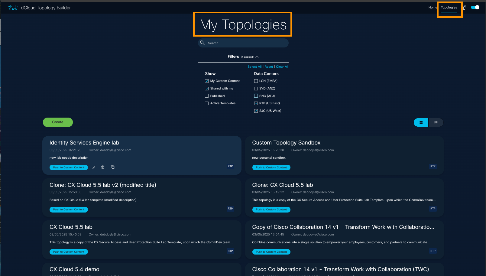
- Click the Title or the Pencil icon below the topology you want to clone.

If you do not see the Pencil icon, click any blank space on the page, and hover over the topology name again.
- Change the Name, Description, and add a helpful Note to identify the Cloned Topology.
- Click Save.
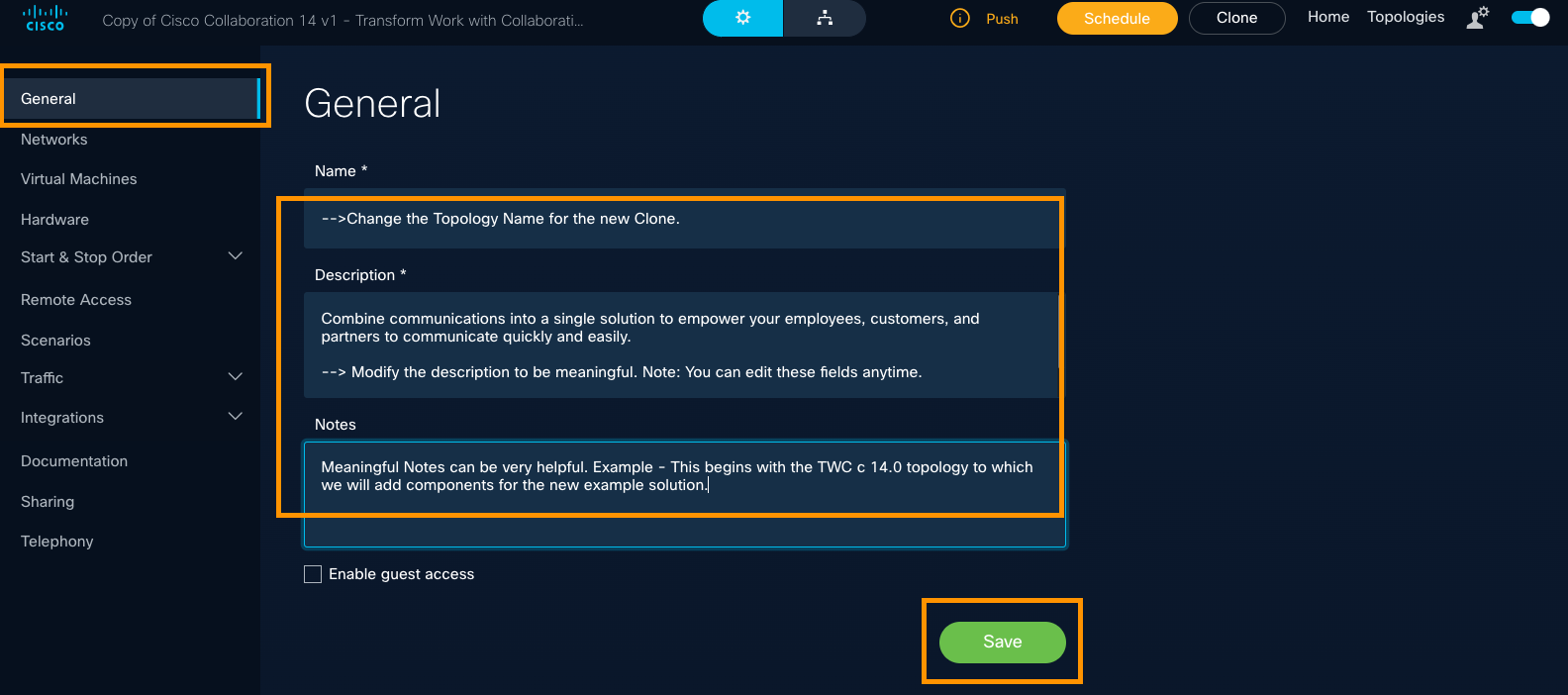
- At the top of the General configuration page for the topology, click Clone (to the right of the Schedule button).
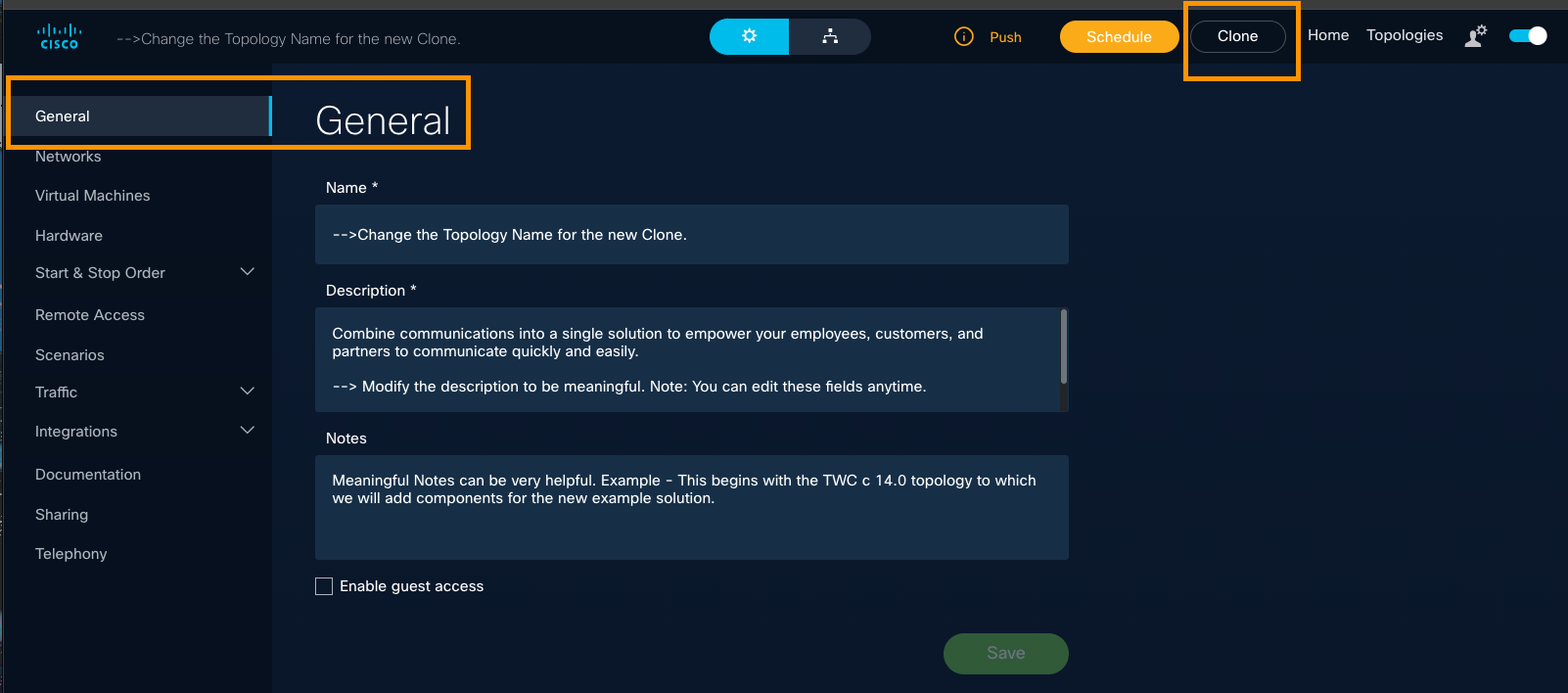
- When the Clone Topology confirmation message appears, change the Name / Description if you did not do this already, and click Create.
Keep in mind you should avoid having two topologies with the same name: Be sure to change the name of the clone to reflect the goal of the content you are developing.
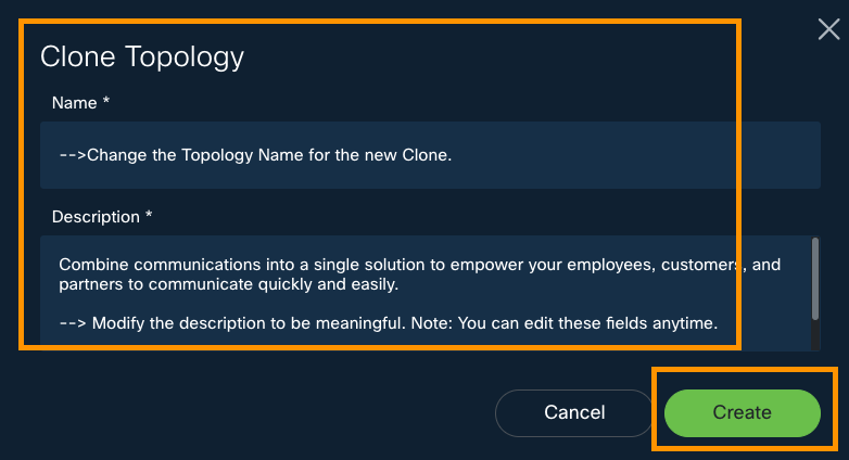
In the confirmation message that displays, click View new topology to return to the General configuration settings page. To explore the configuration options you see on the left-panel menu, scroll down in this guide to the Configure a Topology menu.
The title and description for your new topology (clone) will now display on your My Topologies page.
You can share your topology with other Topology Builder users, and you can share your topology with your customers.
There is a maximum of five (5) simultaneous Saves. If you need more sessions, the content will need to be promoted first.
This content is in progress. Thank you for your patience!
dCloud Topology Builder Release Notes
See what's new & improved in the Topology Builder app.
New in October 2025
The Topology Builder User Guide has been enhanced with the new Configure SaaS Integrations menu that aims to help users quickly connect and configure ThousandEyes, DUO, Cisco Secure Endpoint, and Umbrella integrations to enhance network visibility, security, and operational efficiency.

This new user guide menu is designed to help users enhance demos with integrated SaaS and cloud services to:
- Accelerate setup, simplify access, and deliver compelling, real-world scenarios that resonate with customers.
- Showcase Cisco's comprehensive ecosystem to boost sales and save time by managing integrations directly within your topology for faster, more impactful demonstrations.
New in August 2025
Topology Builder & dCloud Launch Panel Demo developers now have the ability to enable the new Launch panel for scheduled content that has IDAC-hosted recipes configured within the demo. Once enabled in published content, this feature enables users to access IDAC splash pages directly from the Session View page in a tab called “Launch Panel,” rather than through jump hosts.
Topology Builder & dCloud Launch Panel
Demo developers now have the ability to enable the new Launch panel for scheduled content that has IDAC-hosted recipes configured within the demo. Once enabled in published content, this feature enables users to access IDAC splash pages directly from the Session View page (now called "Launch Panel"), rather than through jump hosts.
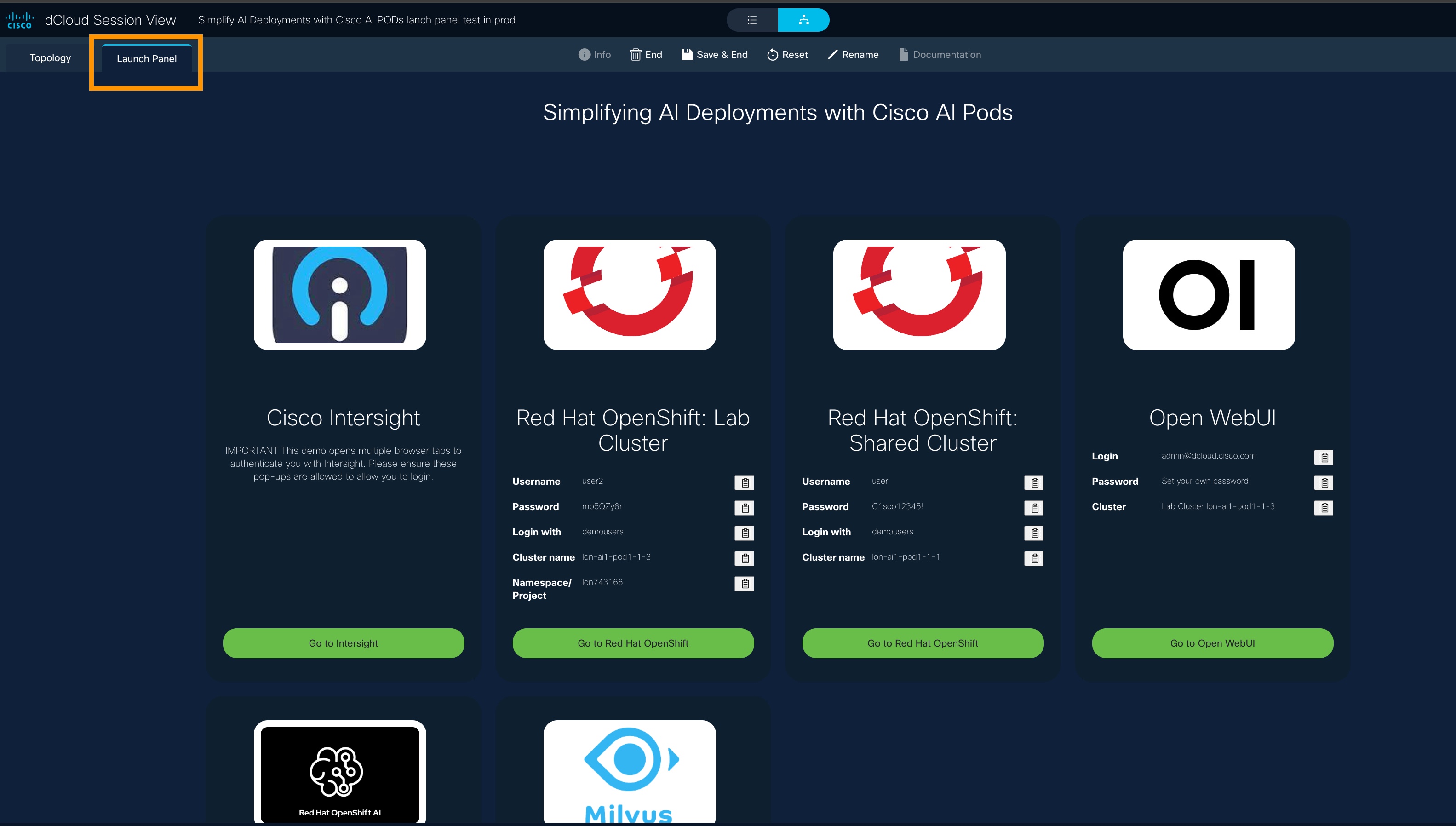
This new feature removes a layer of complexity and empowers you to weave a story across a group of Cisco and third-party applications— without having to look up URLs or remember usernames and passwords.
Download and Watch Quick Video Demo
19 August 2025 - Release 150
What's New in Topology Builder
- Launch Panel feature: We have removed a layer of complexity for Topology Builder users, empowering you to weave a story across a group of Cisco and third-party applications without having to look up URLs or remember usernames and passwords. To incorporate an iDAC splash screen that provides an intuitive experience, Demo Developers can enable a demo for the new Launch Panel from the General page.
- The Launch Panel is for scheduled content that has iDAC-hosted recipes configured within the demo: Once enabled in the published content, users can access iDAC splash pages directly from the Session View page in a tab called "Launch Panel."
New in July 2025
Topology Builder users can now export diagrams in easy-to-view formats, making them ideal for customer-facing presentations, takeaways, or reference materials within documents. For more information, go to the Create a Topology menu and select the Diagram tab.
Export your Topology Diagram to PDF, PNG, & JPG
- At top right of any page, click Topologies to go to (your) My Topologies page.
- Select a topology.
- At top center of the page, find the Toggle button set by default to the gear icon | General configuration page.
- Select the Diagram button to the right to display the topology's Diagram View.
- Click within a blank space on the canvas and then hover over the vertical Diagram Toolbar to see the Export Topology icon.
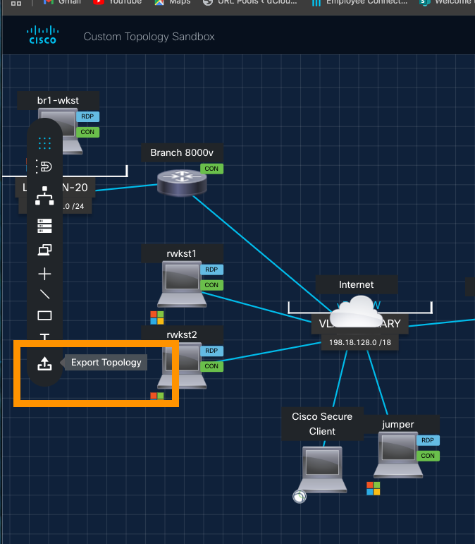
- Select the icon and complete the Export Diagram information:
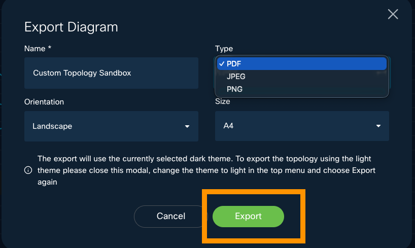
- For more information, go to the Create a Topology menu and select the Diagram tab.
29 July 2025 - Release 147-149
What's New in Topology Builder
- Users can export a Topology Diagram to PDF format to share it with customers and/or keep as a document reference.
- Feedback links are the same as dCloud Feedback links—User feedback forms are all the same (users know what to expect).
- The Request a Feature link is updated—Users are directed to the correct Jira page to raise Topology Builder requests.
What's Fixed in Topology Builder
- Cisco AnyConnect branding has changed to Cisco Secure Client on Topology Diagram Session View.
- Topology Builder Home page has been improved for better user experience—carousel & page wording is clearer.
- After exporting a topology with an asset that is hidden from Session View, the Topology Diagram no longer displays a line extending from the top-left corner of the canvas to the hidden asset.
Release 134-146
Cisco Internal Only
28 April 2025 - Release 133
What's New in Topology Builder
- Topology users can now hide the Guest View checkbox from all but admin users.
30 March 2025 - Release 132
What's New in Topology Builder
- We have removed restrictions on the number of remote connections a user can have in a dCloud session.
- Now, via the Topology Builder application, content creators can build demos in a more flexible manner, with capability of up to 120 connections from the previous limit of 8 remote connections. This feature opens the door for even larger enterprise topologies to run in dCloud. - New icons are added to the library.
- Unused icons are removed from configuration.
What's Fixed in Topology Builder
- VM Start and Stop orders no longer share an ETAG.
- Content Transfer now results in correct demo ID and DC in metrics.
- A 500 error no longer results when a user attempts to delete a topology.
21 March 2025 - Release 131
Cisco Internal Only
18 March 2025 - Release 130
What's New in Topology Builder
- Restrict Guess Access link is now enabled.
11 March 2025 - Release 129
What's New in Topology Builder
- Users can now hide icons (AnyConnect/vPod/Cloud/Endpoint Kit) on the My Topology Diagram page.
- The internal link to Topology Builder v3 Documentation has been updated, to reflect the new User Guide AEM design.
Bookmark the link to this guide for easy reference. If you have questions about or suggestions for this user guide, share your feedback with us.
- Users can now discover Exact Matches for Search criteria.
4 March 2025 - Release 128
Cisco Internal Only
1 March 2025 - Release 127
New in Topology Builder! Generate Guest Access from the General page
To Enable guest access for dCloud sessions on the General configuration page for a topology you have created, follow these steps.
- At top right of any page, click Topologies to open the My Topologies page.
- For the topology you want to enable guest access, select the Pencil icon.
If you do not see the Pencil icon, click on a blank space on the page and hover over the topology name and description again.
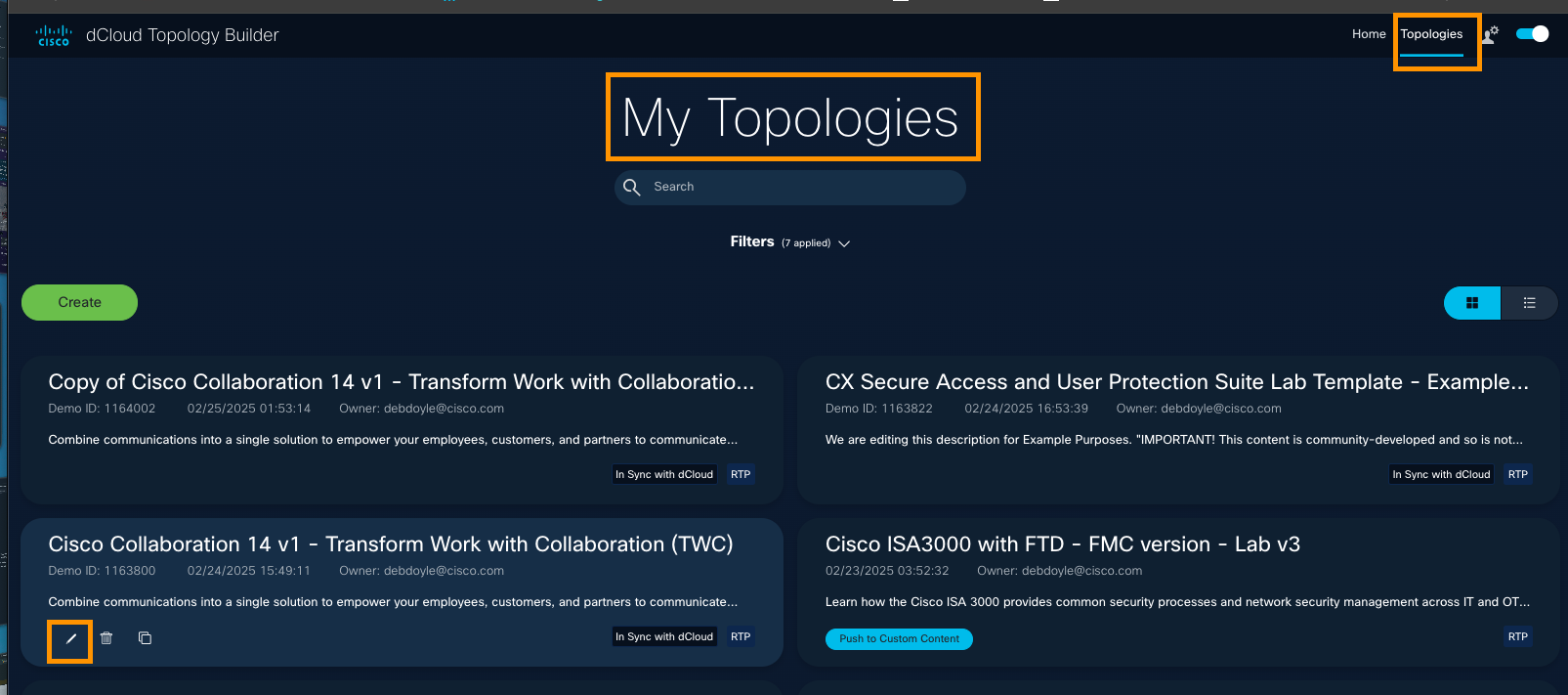
- To give dCloud guests access to your content, check the Enable guest access checkbox.
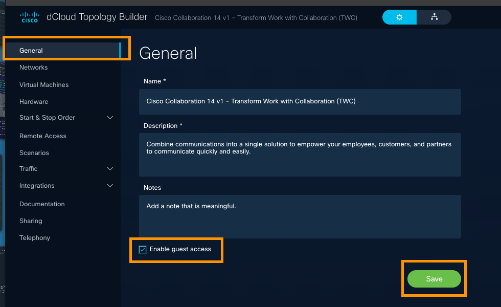
When you check the checkbox and click Save, this feature enables access to dCloud users without CCO credentials to access Session View via a shared link, ensuring they can still benefit from the full demo experience.
Below, you can see the dCloud Session View for an non-CCO authenticated user. Note the limited menu bar options: The user can interact fully with the demo but has very limited control of the session itself.
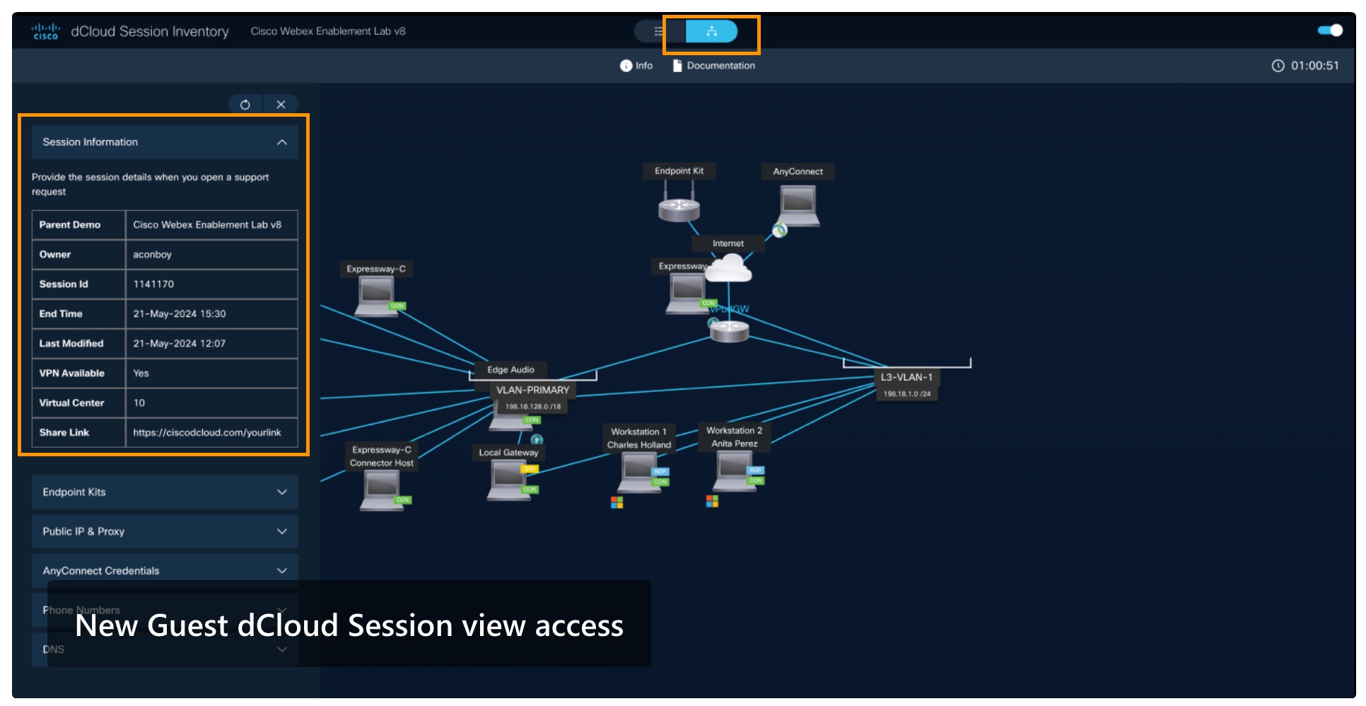
The shared link will need to be passed to those users without CCO credentials.
27 January 2025 - Release 126
Cisco Internal Only
23 January 2025 - Release 125
Cisco Internal Only
20 January 2025 - Release 124
What's New
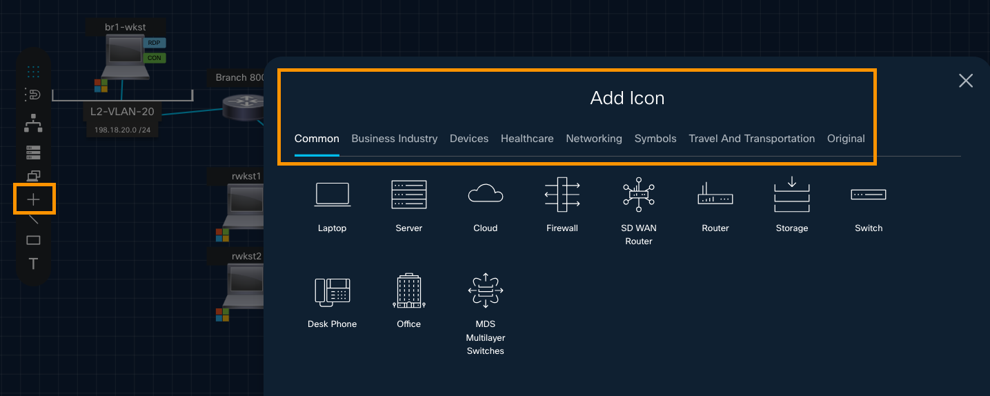
- Now, there is an Icon selector to make it easier to use icons in your topology diagrams.
- VM/Device-Editing icons
- Icons selector added: Add an Icon
- AnyConnect, Cloud, vPod, and Endpoint Kit icons
- New Topology Builder Icon Library demo - video
What's Fixed
- VM Replacement uses new EVC mode.
- Topology ID is checked when pushing to dCloud.
- Topology state persists when you are in Diagram View Edit mode, make no edits, and then cancel the edit.
- SASE icon shows on the Networking tab.
- Edit Network in Diagram View works as expected.
- When you select Hardware in Session View, the Info panel opens.
6 January 2025 - Release 122/123
A new, modern set of Icons, arranged in tabs, is available, based on the Cisco marketing icon set.
![]()
The old icons are also available, in their own tab.
2024 TB RelNotes
5 December 2024 - Release 121
- Users can now clone Topologies: Click the Topology title, click Clone at top right, update the Name/Description if you like, and click Create.
- Topology names are now displayed in the Diagram page header.
- You can click a Schedule button at top of General or Diagram page.
- You can click Push at top of General or Diagram page, to push a topology to dCloud.
- You can change the CPU EVC mode of a VM.
30 October 2024 - Release 118
What's New
- Demo metrics contain the correct published date.
- Improved Virtual Machine (VM) Created Workflow, with unused columns deleted.
Enhancements
Improved user experience in performing the new design actions in Diagram View.
- Draw Lines between connections.
- Use the Telephone icon.
- Use Logical Connection functionality.
16 October 2024 - Release 115
Enhancements
To enable a better Virtual Machine creation workflow experience, unused columns are removed from Add a VM Workflow.
Now, users can change the Default Line Color (even to "transparent"), when drawing lines between Nodes in Diagram View.
When users now use the NAT feature, traffic to the internet is enabled.
5 September 2024 - Release 109
What's New
dCloud Topology Builder users can now perform these tasks in Diagram View:
- Change the font size and color of text labels.
- Rotate the position of text labels.
- Turn on the auto-align option (aligns on the left), and then add new nodes.
15 August 2024 - Release 108
What's New
Users can now configure URLs on Icons added to the Diagram View which then display in the dCloud Session View.
31 July 2024 - Release 106
- Users can now configure internal NAT functionality in their topologies.
- Users can align nodes in Diagram View.
- General
- Networks
- Virtual Machines
- Diagram
- Hardware
- Remote Access
- Traffic
- Push to dCloud
- Advanced
Configure General Settings
To configure your topology at any stage of its development—creation, editing, or when using advanced features—you start on the General Settings page.
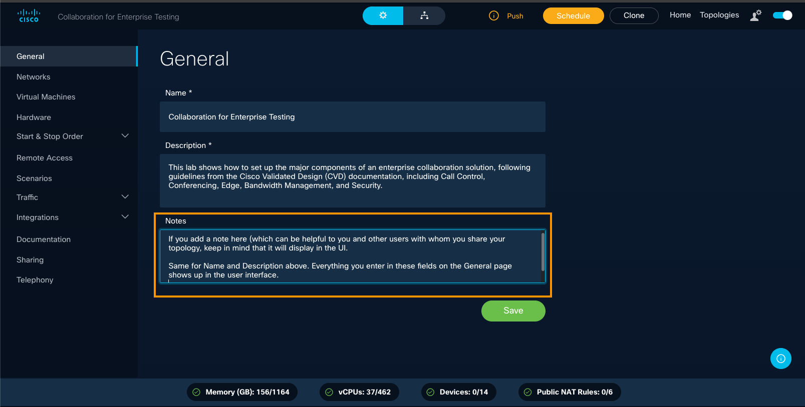
On the General page's General tab, you configure the Topology Name and Description settings and add any helpful Notes.
You can return to this page to make changes as often as needed while developing your dCloud content. Almost every configuration or edit begins on this General page as you navigate through the tabs in the left panel.
To configure General Settings, follow these steps.
- At the top right of any page, click Topologies.
Tip: You can also click Get Started from the Home page to open My Topologies.

- Select a topology to open its General configuration page. The General tab appears at the top left, and the left-panel menu serves as your main navigation while configuring your topology.
3. Fill out the General Page fields.
General Page Fields
Field Description Required | Optional Name Topology name Required Description Meaningful description
Required Notes Useful comments for yourself and others Optional Tip: Include keywords and version numbers in your description to make this topology easy to find. Use clear, descriptive language in these fields, as the information you enter will be displayed in the UI to help identify your topology.
4. When finished, click Save. You can edit these fields at any time.
Enable Guest Access from the General page
To enable guest access for dCloud sessions from the General configuration page of a topology you have created, follow these steps.
- At the top right of any page, click Topologies to open the My Topologies page.
- For the topology for which you want to enable guest access, click the Pencil icon to edit.
If you do not see the Pencil icon, click a blank space on the page, then hover over the topology name and description again.

- To give dCloud guests access to your content, check the Enable guest access checkbox.

When you check the box and click Save, users without Cisco Customer Connection (CCO) credentials can access Session View via a shared link, enabling them to benefit from the full demo experience.
You will need to share this link with users who do not have CCO credentials.

Above, you can see the dCloud Session View for an non-CCO authenticated user. Note the limited bar options. The user can interact fully with the demo, but has very limited control of the session itself.
View & Configure Networks
Learn how you can view the default network, add a new network to your topology, edit or hide a network, or delete a network, using Topology Builder.
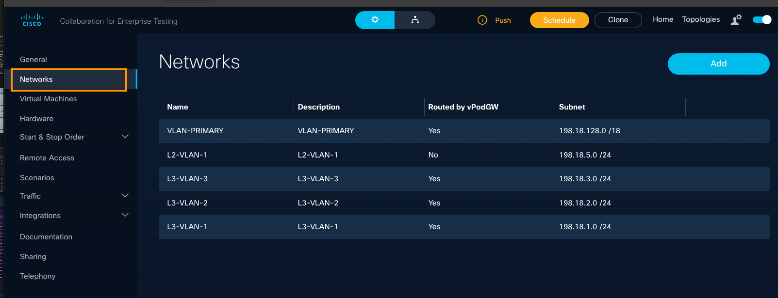
On the Networks page, you can view the default network already configured; add a new network to your topology; edit and/or hide a network or delete a network.
- At the top right of any page, click Topologies.

- On the My Topologies page, select a topology: Click the title or the Pencil icon, to open the topology's General settings page.
If you do not see the Pencil icon, click once in any blank space and then hover above the topology info. and try again.
- On the left panel of the General page, select Networks.
View the Default Network
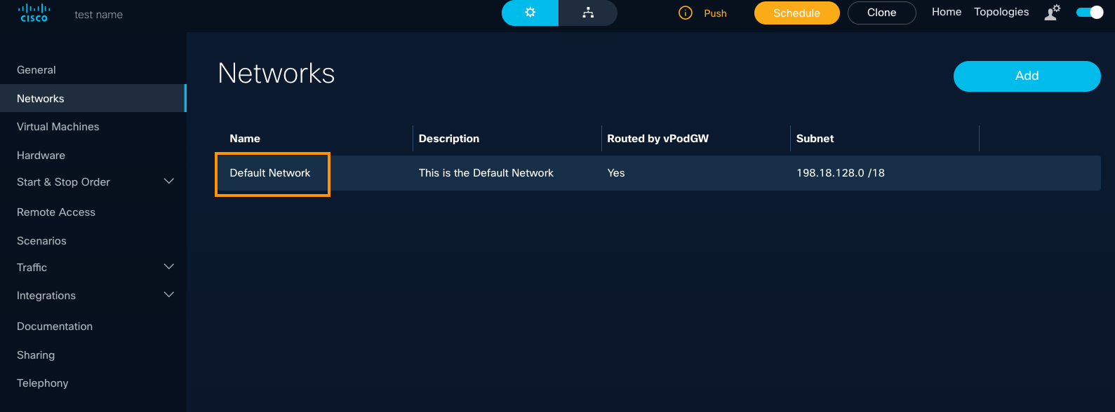
The Default Network is automatically added to a topology you create. It will be directly attached to the vPodGW and will use IP subnet 198.18.128.0/18.
- Click Topologies at the top right of any page.
- On the My Topologies page, select a topology to open its General configuration page.
- On the left panel of the General page, select Networks.
- View the pre-configured Default Network for your new topology.
Add a Network to your Topology
To add a network to a topology, follow these steps.
- Click Topologies at the top right of any page.
- On the My Topologies page, select a topology to open its General configuration page.
- On the left panel of the General page, select Networks.
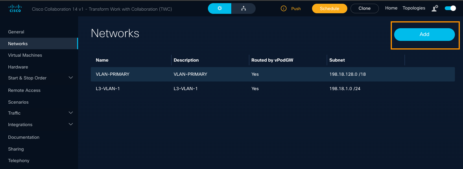
- On the right side of the page, click Add.
- Enter information for the network you want to add.
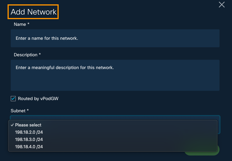
Tip: Keep in mind that everything you add in these fields displays in the UI.
Add Network Actions In this field... do this...
Required | Enabled by default Name Enter a network name.
Required Description Enter a meaningful description.
Required Routed by vPodGW If N/A, you can uncheck this box. Automatically enabled by default Subnet In the drop-down, select the Subnet for this network. Required - Click Add.
The network is added to the topology.
Edit/Hide a Network
You can quickly edit a network and/or hide it from the Topology Diagram.
- At top right of any page, click Topologies.
- On the My Topologies page, select the topology title or click the Pencil icon to edit or hide a network.
- On the left panel menu on the General configuration page, select Networks.

- Click the Pencil icon to edit this network. If you do not see the Pencil icon, click within a blank space on the page, and hover over the list again.
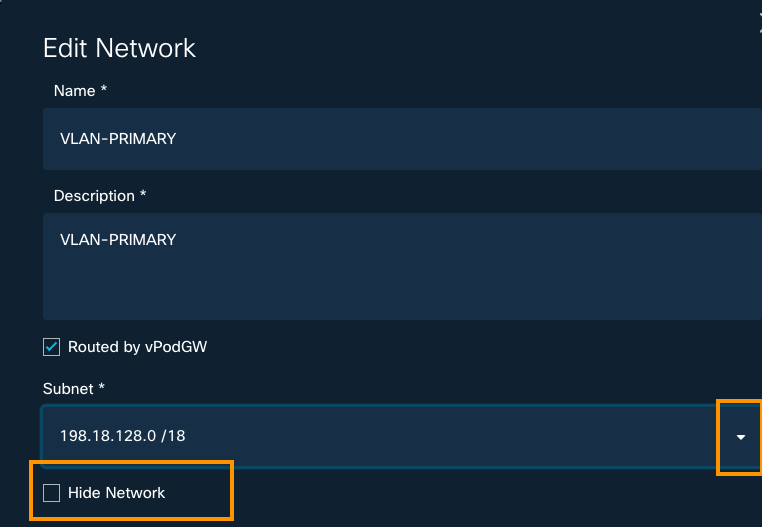
- Edit the Network Name and Description, if needed.
- To edit a Subnet, click the arrow to open drop-down menu, and select an option.
- If you don't want this network to appear in your Topology Diagram, check the Hide Network checkbox.

- To commit your changes, click Update.
Delete a Network
To delete a network from a topology, follow these steps.
- At top right of any page, click Topologies.
- On the My Topologies page, select a topology in the list to display the General configuration page.
- On the left panel menu, click Networks.
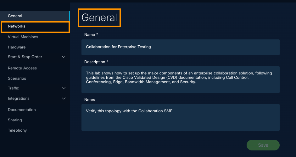
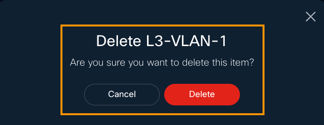
- On the Networks page, hover over the network you want to delete, and click the Trashcan icon.

- If you're sure, click Delete.
Discover & Configure Virtual Machines
To enable dCloud users to complete demo activity, you will configure VMs within your topology.
You can configure VMs to host new applications or software presented as part of a customer demonstration, to drive value for your customer's best business outcomes.

You can quickly search for VMs by version and other keywords, architecture, and those not identified for a specific architecture.
In Topology Builder are many available VMs. Some are prebuilt and configured for dCloud content. There are also copies of VMs from existing dCloud demos.
You can use Topology Builder in the dCloud production environment to quickly copy all or selected VMs from a published dCloud project into a new demo configuration you can customize and deploy to meet your customer's business objectives.
VM Templates are the building blocks of our demos.

To save your development time, our engineers have built and tested hundreds of solutions you can reuse or leverage for your dCloud demos.
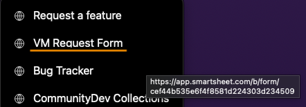
Want to request a VM Template? It's easy.
- Go to the Community Webex Space.
- Mouse over the +4 dropdown menu.
- Click VM Request Form.
Add a Virtual Machine
To add a VM to your topology, follow these steps.
- At top right of any page, click Topologies.

- On the My Topologies page, click the title or select the Pencil icon for the topology.
If you do not see the Pencil icon, click once within a blank space on the page, and hover again.
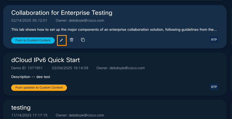
- On the left panel of the General page, click Virtual Machines.
- Click New.
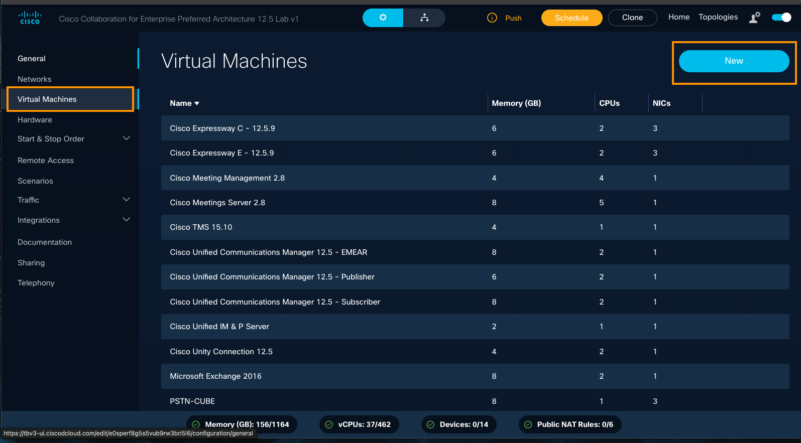
- Select a Virtual Machine from either the VM Templates list or the Demo Templates list.
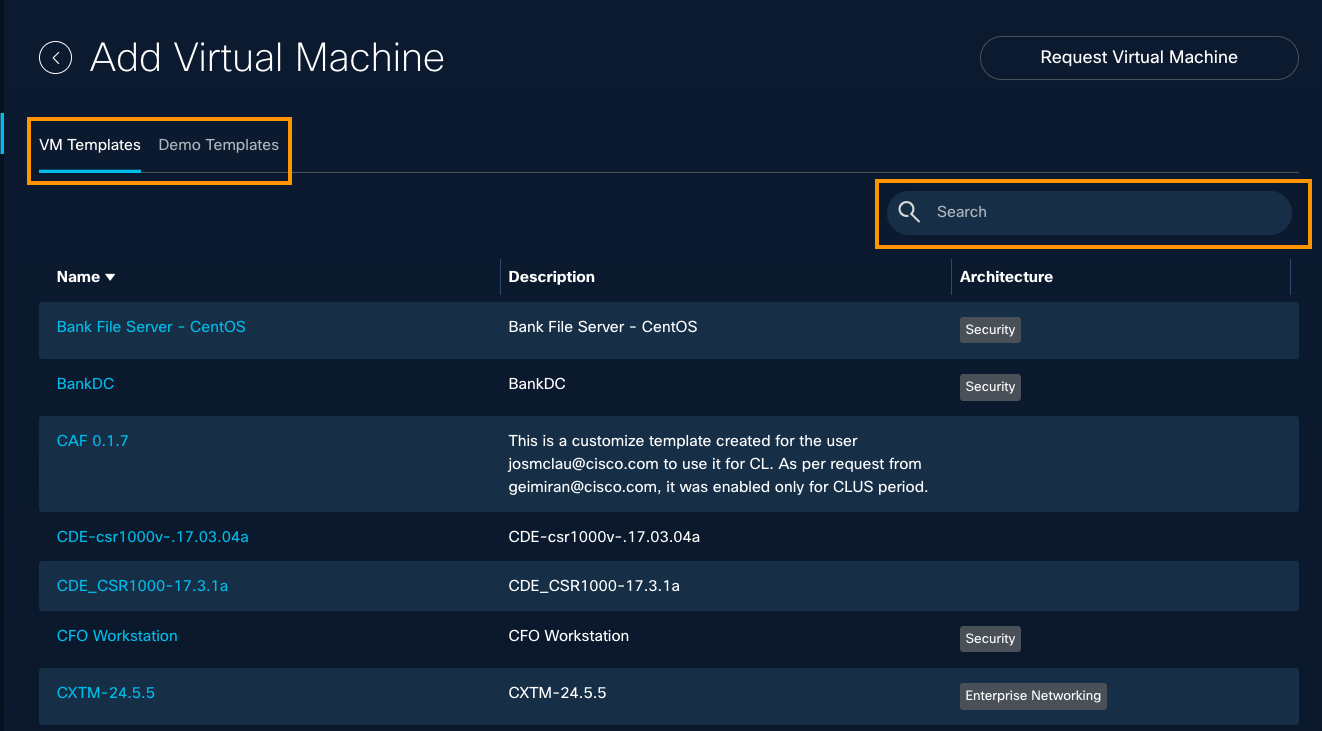
- To narrow your results, try searching for a version number (such as "2.0") or more specific keyword.

- If you do not see the VM you want, click Request Virtual Machine at top right, complete the dCloud Topology Builder Template Request form, and click Submit.
Configure VM Start and Stop | Hardware Start order
You can configure the order in which virtual machines are started or stopped, and set the Hardware Start order within a running demonstration, by updating the default settings.
| Order Type | Default Setting | Result |
| VM Start Order | Concurrent | VMs within the topology start at the same time. |
| VM Stop Order | Unordered | VMs within the topology stop at the same time. |
| Hardware Start Order | Unordered | Hardware devices start at the same time. |
Set VM Start Order
Default Start Order of virtual machines is set to Concurrent, which means all virtual machines within a topology start at the same time.
To set the Virtual Machine (VM) start order, follow these steps.
- At top right of any page, click Topologies.
- On the My Topologies page, hover over the topology for which you want to view or configure the VM Start order, and click the Pencil icon.
- On the left panel of the VM Start page, select Start & Stop Order, and then click VM Start.
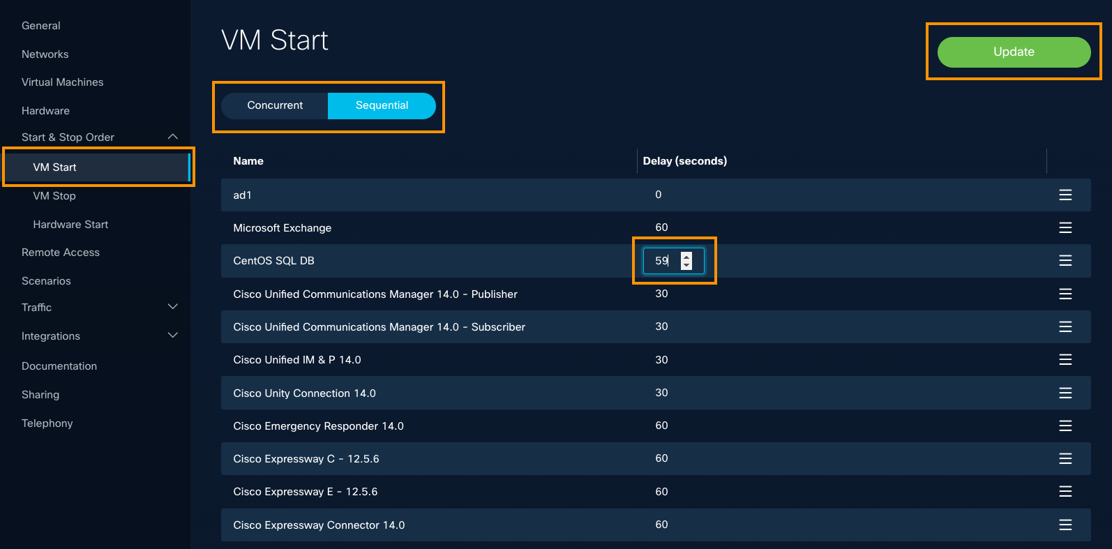
- On the VM Start page, you can configure the VM Start to be Concurrent or Sequential.
- In the Delay column, select several seconds to increase or decrease the delay.
- Click Update.
Set VM Stop Order
Default Stop Order of virtual machines is set to Unordered, which means all virtual machines within a topology stop at the same time.
It may be necessary to stop the Virtual Machines (VMs) in a specific order, when a demonstration has ended.
Default Stop Order of virtual machines is set to Ordered, which means all virtual machines within a topology stop at the same time.
To set the Virtual Machine (VM) Stop order, follow these steps.
- At top right of any page, click Topologies.
- On the My Topologies page, hover over the topology for which you want to view or configure the VM Stop order, and click the Pencil icon.
- On the left panel of the VM Start page, select Start & Stop Order, and then click VM Stop.
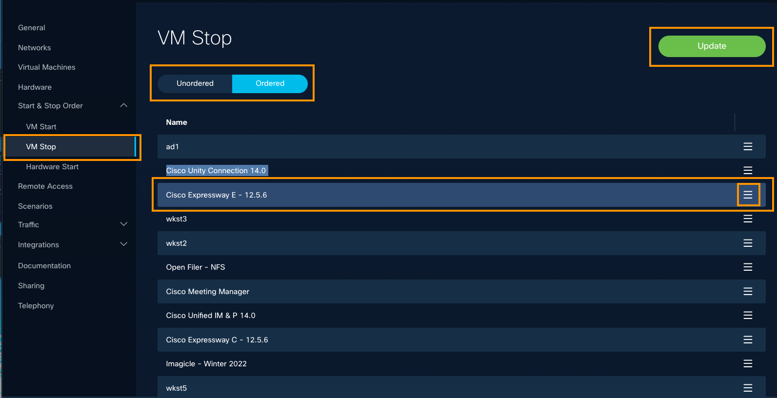
- On the VM Start page, you can configure the VM Start to be Concurrent or Sequential.
- To move a VM up or down in the ordered list, click the three lines at the right and drag it up or down.
- Click Update.
Edit a Virtual Machine
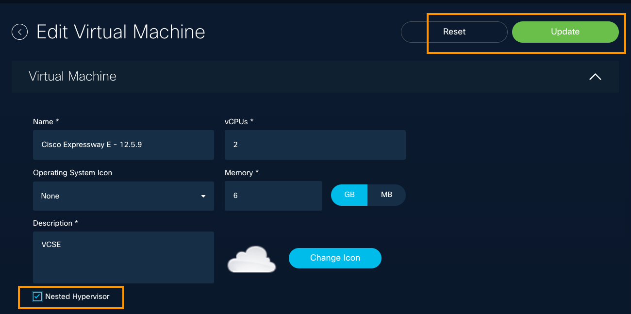
To edit the Name and Description of the virtual machine, the virtual machine CPUs, Memory allocated, follow these steps. You can also use this feature to select an Operating System icon and enable Nested Hypervisor functionality.
- At top right of any page, click Topologies.

- On the My Topologies page, hover over a topology, and click the Topology Name or the Pencil icon.
If you do not see the Pencil icon, click once within a blank page space, and hover again.
- On the left panel of the General page, click Virtual Machines.
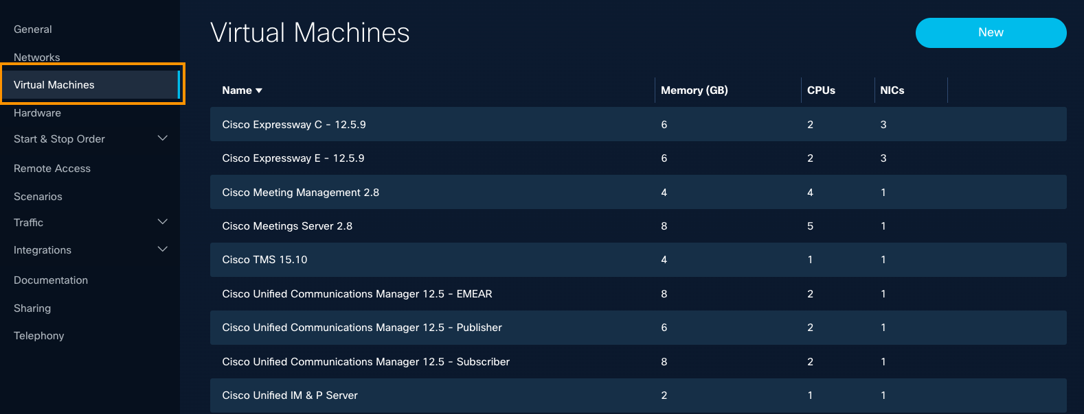
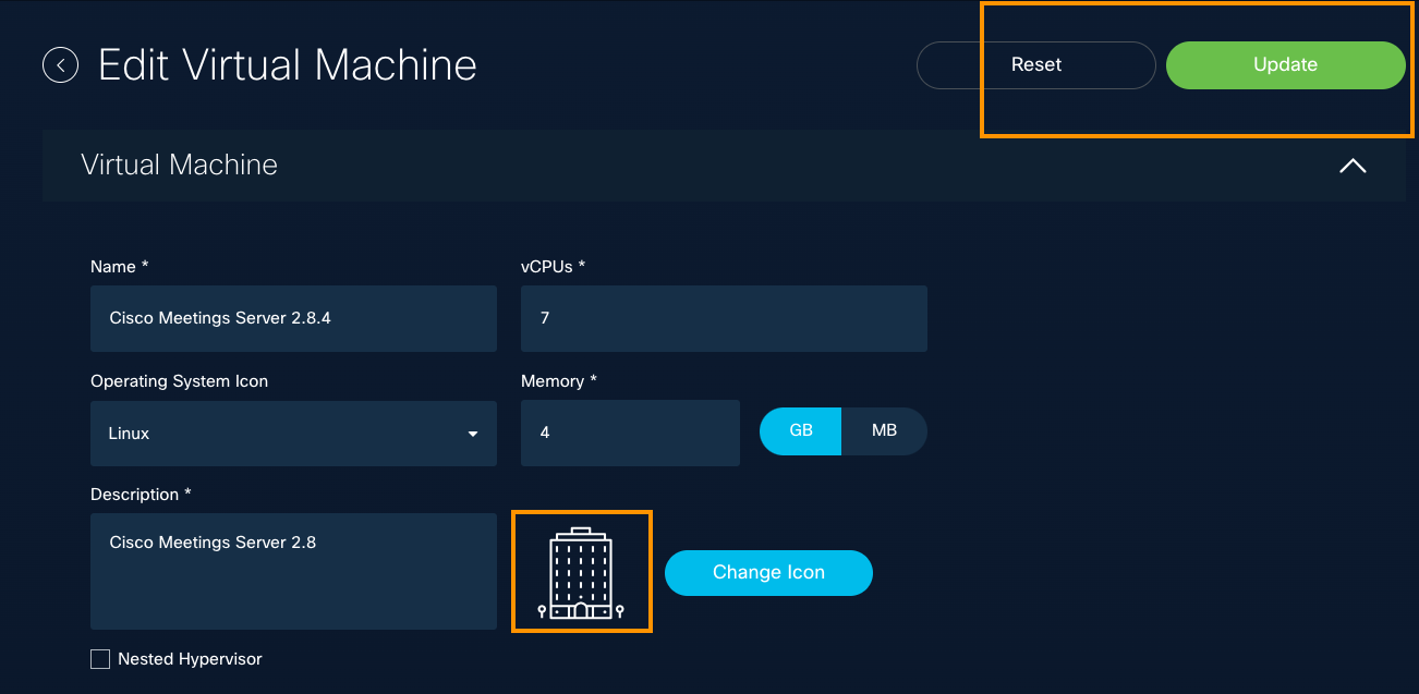
- On the Edit Virtual Machine page, you can update any field that displays. As you begin editing, the Reset and Update buttons at top right become active.
You can edit these fields:
Name | Operating System Icon | vCPUs | Memory | Description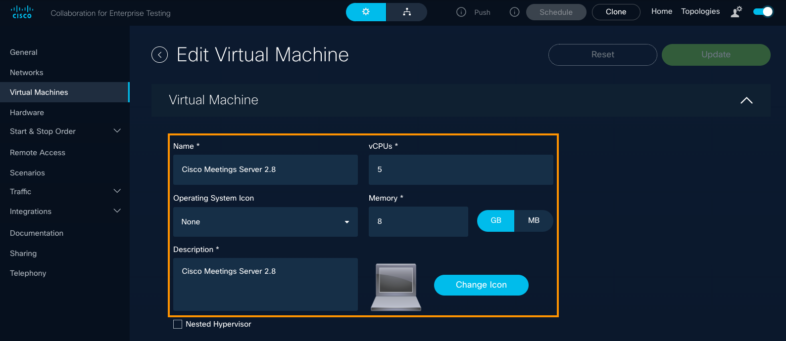
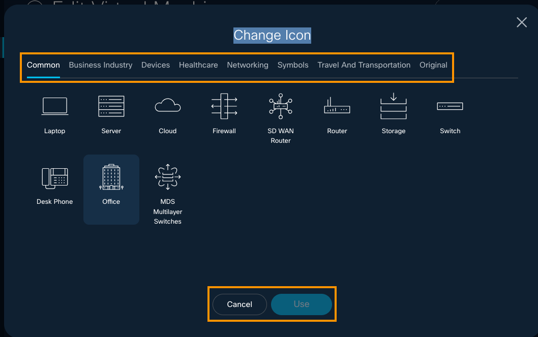
- To select a different option in the Icon Library, click the Change icon and change the original Laptop image to the Office symbol on the Common tab.
Easily design the look and feel of your Topology Diagram. Watch the New Icon Library demo video.
- Click Use.
Example: Edited VM - Review the example below, to see every field edited, including the changed icon.
- To enable Nested Hypervisor functionality, check the checkbox.
Hypervisor References
- Catalyst SD-WAN Compatibility Matrix & Recommendations
- Catalyst SD-WAN 20.15 Custom Topologies Lab
- Catalyst SD-WAN Getting Started Guide
New! Generate Guest Access from the General page
This new feature is typically used for Events and demand generation activity where users may not have a CCO account.
.To Enable guest access for dCloud sessions on the General configuration page for a topology you have created, follow these steps.
- At top right of any page, click Topologies to open the My Topologies page.
- For the topology you want to enable guest access, select the Pencil icon.
If you do not see the Pencil icon, click on a blank space on the page and hover over the topology name and description again.

- To give dCloud guests access to your content, check the Enable guest access checkbox.

When you check the checkbox and click Save, this feature enables access to dCloud users without CCO credentials to access Session View via a shared link, ensuring they can still benefit from the full demo experience.
The shared link will need to be passed to those users without CCO credentials.

Above, you can see the dCloud Session View for an non-CCO authenticated user. Note the limited menu bar options: The user can interact fully with the demo but has very limited control of the session itself.
Edit a Virtual Machine - Guest Automation
With Guest Automation, you can execute commands upon the VM start, have dCloud session parameters on the session VMs run a startup script on the VM, and more.
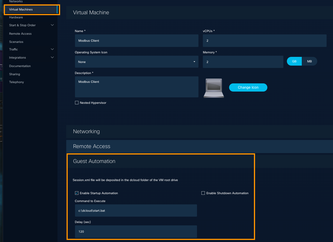
Complete the four Prerequesites below, to prepare for Guest Automation.
If you have questions, we encourage you to visit the dCloud Topology Builder Community space, to get insight from experienced users and subject matter experts.
Guest Automation: Before you begin
Follow these Prerequisites, based on best practices, before you edit VM Templates and or add VM Templates from scratch, as you develop your dCloud demo for Guest Automation.
Prerequisites
- On the VM, install the required dependencies (Python, required modules, libraries, etc.).
- Install the software for all users, not only for the administrators.
- Do not use spaces in folder names (not "folder" name but "foldername").
- Do not rely on the OS path. Use the full path to the executable files and scripts.
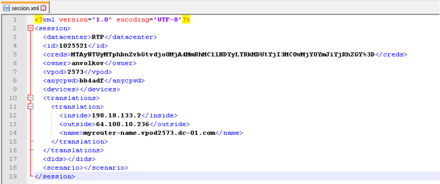
Enabling Guest Automation generates the session.xml file with all session details. This file includes the unique per-session parameters, such as current session ID, AnyConnect Credentials, assigned devices and licenses, public IP addresses (1-1 NAT), public DNS records, etc.
- Find the session.xml file in the following locations:
Linux VM: /dcloud/session.xml
Windows VM: C:\dcloud\session.xml
Example: session.xml content
<?xml version="1.0" encoding="UTF-8"?>
<session>
<datacenter>RTP</datacenter>
<id>1025521</id>
<creds>MTAyNTUyMTphbnZvbGtvdjo0MjA4MmRhMC1lNDYyLTRkMDUtYjI3MC0wMjY0YmJiYjRhZGY%3D</creds>
<owner>anvolkov</owner>
<vpod>2573</vpod>
<anycpwd>bb4adf</anycpwd>
<devices></devices>
<translations>
<translation>
<inside>198.18.133.2</inside>
<outside>64.100.10.236</outside>
<name>myrouter-name.vpod2573.dc-01.com</name>
</translation>
</translations>
<dids></dids>
<scenario></scenario>
</session>
- Additionally, you can specify the command that will be executed upon the VM start. The command can include anything which can be used in the Command Line of the VM.
Before you add a command to Guest Automation, run it in the VM CLI for tests:

For example, you can use this Guest Automation command to execute a startup script:
C:\Python311\python.exe C:\Scripts\myscript.py

Tip: For scripts running longer than 12 minutes, it is best practice to execute from the Windows Startup folder. Then, you will not need to be concerned about it timing out before you are done.
Configure Guest Automation
To configure Guest Automation for a VM, follow these steps.
- At top right of any page, click Topologies.
- On the My Topologies page, hover over the topology for which you want to enable Guest Automation, and click the Pencil icon to edit. Optionally, you can click the Topology Title.
- On the General configuration page, select Virtual Machines in the left pane.

- Hover over the VM that you want to configure, and click the Pencil icon.
- Click Guest Automation to open the menu.

- Make your selections.
Edit Advanced VM Settings
To configure Advanced Virtual Machine settings, follow these steps.
- At top right of any page, click Topologies.
- On the My Topologies page, hover over the topology for which you want to enable Guest Automation, and click the Pencil icon to edit. Optionally, you can click the Topology Title.
- On the General configuration page, select Virtual Machines in the left pane.

- Hover over the VM that you want to configure, and click the Pencil icon.
- Scroll down a bit, and click Advanced Settings to open the menu.
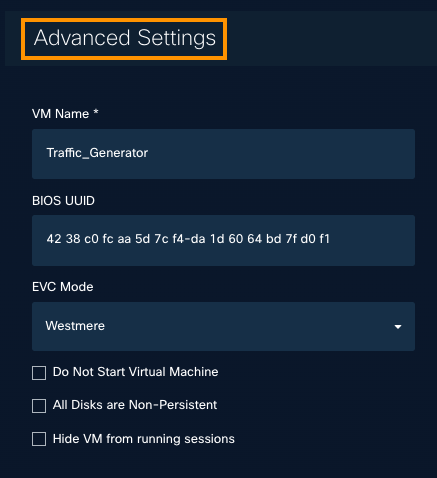
- Change the settings:
VM Name
Change the name in the VMware virtual center.BIOS UUID
Change the BIOS UUID, as required, for software licensing policy.Do Not Start Virtual Machine
VM will not start when the session is run, and may require manual startup.
- All Disks are Non-Persistent
When you enable this feature on a VM and the demo starts, all disks go into Non-Persistent mode.
Configuration edits you make during Non-Persistent mode will not be saved.
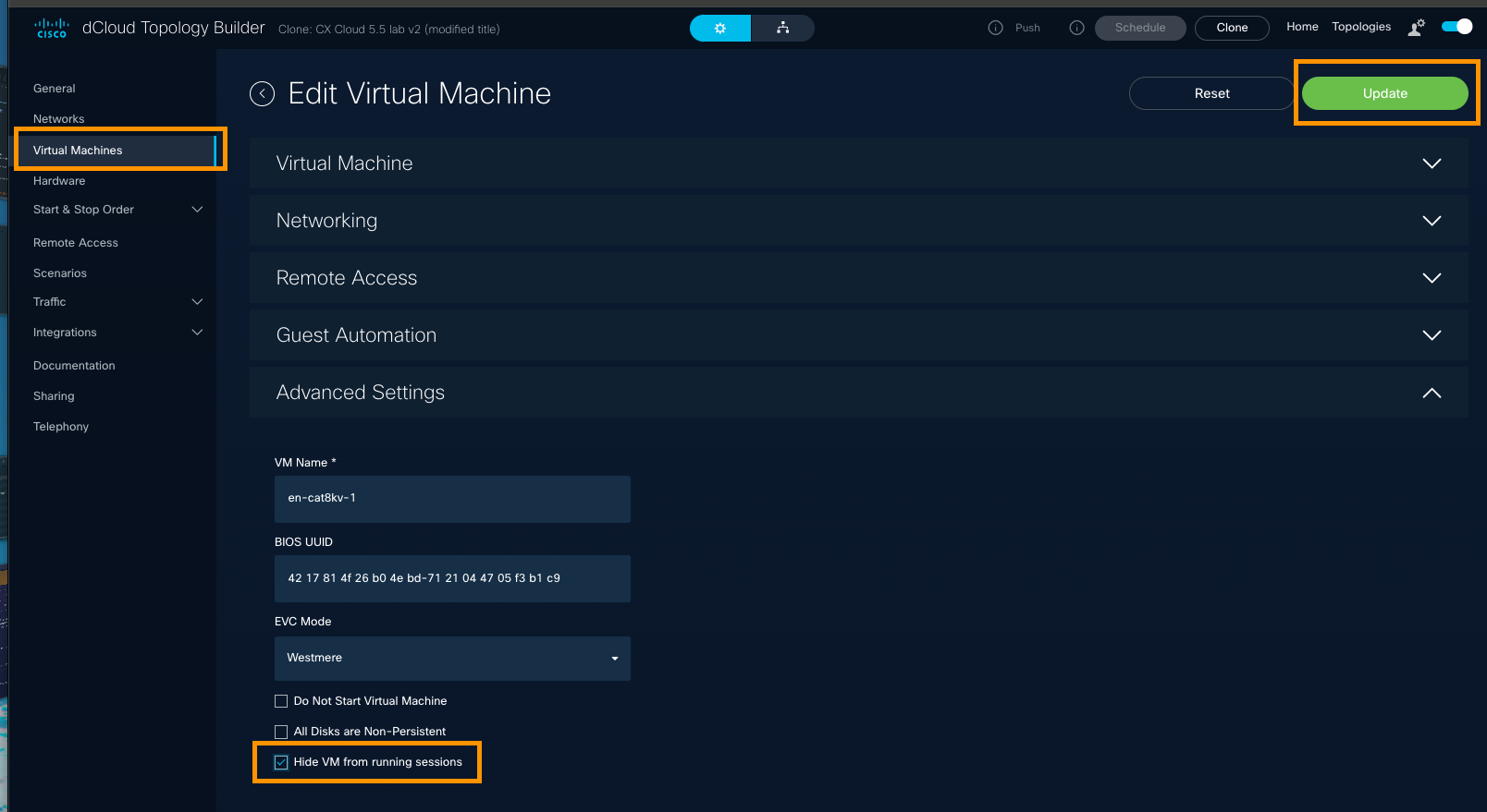
- Hide VM from running sessions
Result: the VM is powered down and back up again, and resets to the time before you attempted to make recent changes.
To ensure the VM changes you made will persist when you share the topology, do not select the Non-Persistent option.
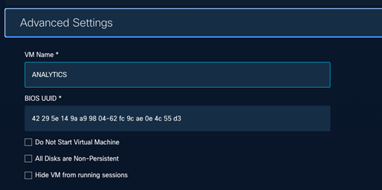
- Hide VM from running sessions
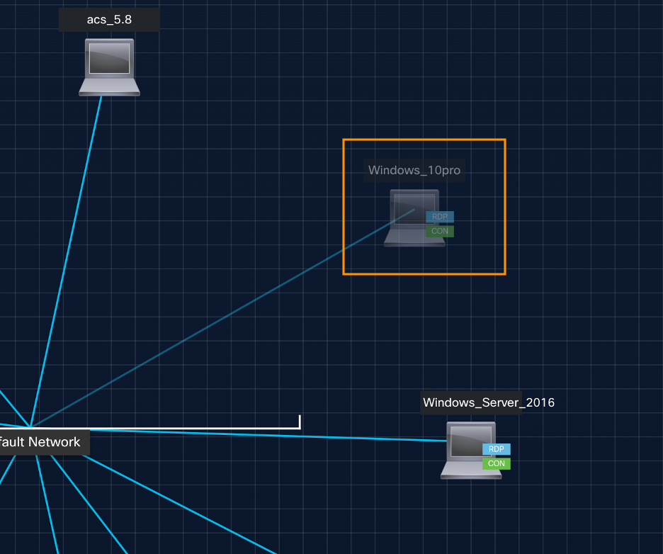
When you run the Topology from dCloud, a user is unable to view this virtual machine in the running sessions of the demo.
When you view this change in Diagram View, the VM and its connection line will be greyed out and not visible from the Session View when the demo is scheduled and running in dCloud.
Enable DHCP
You can assign the IP addresses of your NIC to your VMs, regardless of the network where the NIC lives. You can set the Network, NIC Type, MAC Address, and IP address for the VM and enable DHCP to automatically apply the configuration.
- At the top right of any page, click Topologies.
- On the My Topologies page, hover over a topology to display the Pencil icon on the right, and select it.
- In the left menu, select Virtual Machines.
- Hover over a VM and click the Pencil icon to edit its configuration.
- Click Networking and observe the list of NICs assigned to your VM Template.

- Select a Network, NIC Type, MAC Address (Optional), and IP Address. We allow a single, default gateway you can configure when you have populated these fields and enabled DHCP.
Note:For a NIC you edit or a NIC you add, specify an IP Address that matches the network you have selected. The IP Address must be within the range of the network.
Delete a Virtual Machine
To delete a virtual machine from a topology, follow these steps.
- At top right of any page, click Topologies.
- On the My Topologies page, select a topology that includes the vm you want to delete.
The topology you selected opens on the General configuration settings page. - On the left panel of the General page, click Virtual Machines.
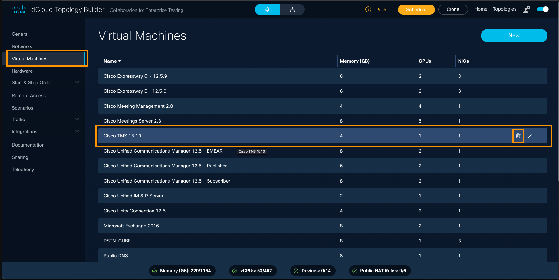
- Hover over a VM you want to delete, and click the Trash icon to the right.
If you do not see the Trash icon, click within any blank space on this page and hover again.
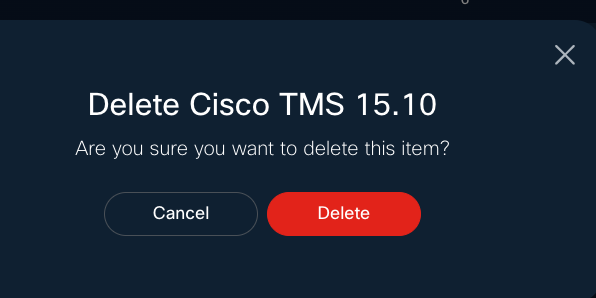
- If you are sure you want to delete this VM, click Delete.
Configure Scenarios - Advanced Feature
Empower dCloud users to choose which scenario they'd like to experience in which order. This feature enables a quality user experience in less time than it takes to watch the demo from start to finish.
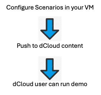
Review the Enabling and Configuring Scenarios topics that follow. Then, learn potential uses for the Scenarios feature.
Enable Scenarios
Scenarios, when enabled in your Topology, configured in your Virtual Machine, and pushed to dCloud custom content, are available to select upon scheduling from dCloud. This topic explains how to enable Scenarios. The topic following this one describes how to configure them within a VM.
Configure Scenarios within a Virtual Machine
Now that you have enabled Scenarios, you can configure them within a Virtual Machine. To do this, you need to run the Topology you’ve created on dCloud and configure the scenarios with a custom-created script.
In this example, you will create two scenarios using a simple PowerShell script that defines to which site Chrome goes each time you log on to the Windows VM RDP connection. This is based on the Scenario selected by the user who is launching the dCloud session.
Scenarios do not work on Hardware devices. If you need guidance on how to configure in Linux, please reach out to our dCloud Topology Builder Community.
Scenarios: Current and Potential Uses
Currently, there is a dCloud lab that parses the scenario and executes in-demo automation based on user selection. To see this in action, visit Cisco IOS XR Enablement - Multilab Sandbox v1. Additional Uses for Scheduled Tasks are in progress and will be added soon.
Following are some potential uses for the Topology Builder Scenario functionality:
Multi-day Labs: A lab can require multiple configurations, such as day 1 config, day 2 config, and so on and so forth. Each day can be configured to include a specific scenario, and the automation can trigger/configure the baseline per the user's selection by parsing the session.xml file.
A and B Testing: Testing between lab configurations is like Multi-day Labs (above) but illustrates an A configuration vs. a B configuration, based on the user's selection by parsing the session.xml file.
CML Use in Walk-In, Self-Paced Labs: While CML has five labs currently registered, a single, specific lab can auto-launch based on a user's selection by parsing the session.xml file.
Great job!
You have learned how to view and discover networks and virtual machines and networks and how to add and edit them. Well done!
Next, you will learn how to design your topology diagram to show how everything fits together. Diagrams are a great sales tool that enables your customers to understand the HOW of a Cisco solution that makes the WHY (customer business outcomes) possible.

Design My Topology Diagram
Enhance your customer engagement with a clear topology diagram that is easy to follow and increases your customer's confidence in Cisco. To create a Topology Diagram, click the toggle at top of any configuration page.
![]()
Then, use the Diagram Toolbar to manipulate your diagram. With an easy user interface, you will find it a fun and creative activity.
Keeping your customer's best outcomes top of mind, as you design your diagram, will bring your customer's solution story together in a fresh way that clarifies the Cisco solution's framework. A well-showcased Topology Diagram can increase customer confidence.
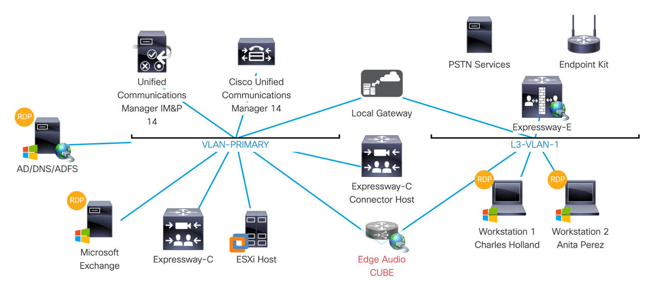
Edit Your Topology Diagram
To edit your Topology Diagram, follow these steps. Also see "Discover the Icon Library" topic that follows this one.
- When you have created a topology, click the Diagram icon to toggle to Diagram View.

- Use the vertical Diagram Toolbar on the left to experiment with ways you can enhance the look and feel of your Topology Diagram.
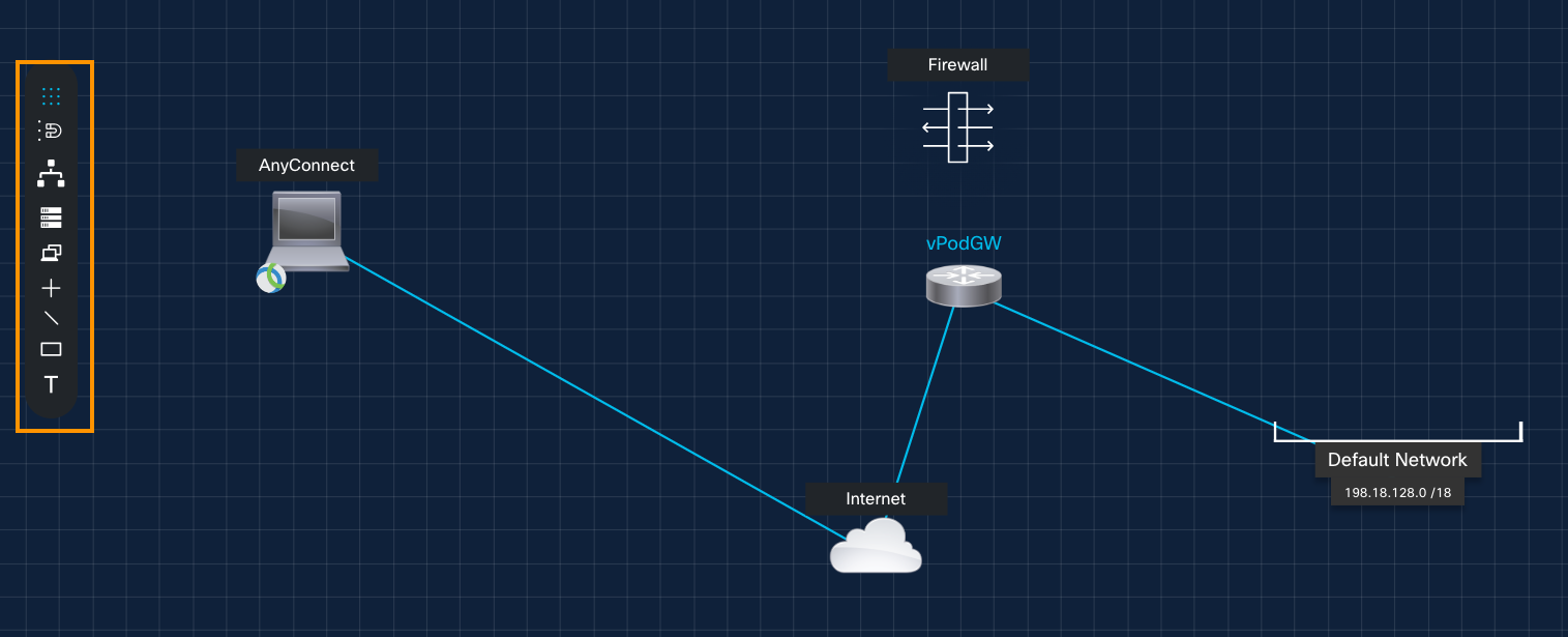
- Select the Diagram Tools to perform these actions:
| Tool | Option | Action |
 | Hide/Show grid | Hide or Show the grid as the page background. |
 | Enable/Disable auto-align | Disable or Enable automatic alignment. |
 | Add Network | Add a new Network. |
 | Add Hardware | Add new Hardware. |
 | Add VM | Add a Virtual Machine. |
| Add Icon | Select an icon from the Icon Library. | |
 | Add a Line | Draw lines to connect nodes. |
 | Add a Box | Resize and move box into your diagram. |
 | Add Text | Add Text inside a box. |
Hide Icons on your Diagram
When you hide an icon on your topology diagram, any connection lines attached will also be hidden in dCloud Session view.
You were already able to hide multiple icons on your diagram, and now you can hide more. To hide the AnyConnect / vPod / Endpoint Kit icons so they do not appear on your topology diagram, follow these steps.
- Hover above the icon you want to hide, and click the Pencil icon.
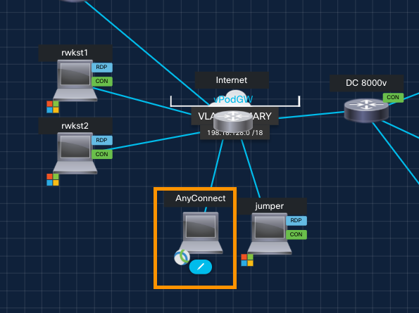
- Check the Hide from running sessions checkbox, and click Save.
![]()
Discover the Icon Library
You can customize the way your Topology looks and feels to enhance your customer engagement. Designing your topology diagram is easy and effective, for the simplest to the most complicated topology.
![]()
For a mini-tutorial, watch the New Icon Library demo.
New! Export your Topology Diagram to PDF, PNG, & JPG
Export diagrams in easy-to-view formats, making them ideal for customer-facing presentations, takeaways, or reference materials within documents.
- At top right of any page, click Topologies to go to (your) My Topologies page.
- Select a topology.
- At top center of the page, find the Toggle button set by default to the gear icon | General configuration page.
- Select the Diagram button to the right to display the topology's Diagram View.
- Click within a blank space on the canvas and then hover over the vertical Diagram Toolbar to see the Export Topology icon.

- Select the icon and complete the Export Diagram information:

- Confirm these parameters, then click Export.
- Name, Orientation (Landscape, Portrait)
- Size (A4, Letter, 11x17)
- Type (PDF, JPEG, PNG)
To effectively use the image in your presentation, as take-away material, and as the Cisco solution design for your demo story, consider the following approach:
Using the Image in a Presentation
- Talking Points emphasizing how the solution is built to address customer challenges and drive high business value.
- Slide Integration to reinforce the narrative of your demo.
As Take-Away Material
- Leave-Behind Document: Include the image in a one- or two-page solution brief or summary document that customers can refer to after your presentation.
- Highlight Value: Annotate or caption the image to clarify how the solution components work together to deliver business value.
- Easy Reference: Create a high-quality, visually appealing Topology Diagram for take-away material that is easy to understand, helping customers recall the demo story and Cisco’s value proposition.
As Cisco Solution Design for Your Demo Story
- Solution Blueprint: Cisco solution design that underpins your demo, showing the integrated components and their roles.
- Business Value Focus: Align the design with the customer’s business outcomes, demonstrating how Cisco’s technology solves their specific challenges.
- Confidence Builder: This visual of the Cisco technology behind the solution helps make the demo story compelling and credible.
By leveraging the Topology Diagram in these ways, you create a cohesive and impactful narrative that showcases the infrastructure powering Cisco’s solutions that bring high business value to your customers.
Diagram Tips
Here are some tips, and we would love to hear yours! Click the Give Feedback banner on the right and share with us, and we'll update this guide so the community benefits.
- Illustrate the HOW that brings your customer's best business outcomes.
- Customize for clarity - Design simply, to make the solution more intuitive.
Diagram Tricks
- To prevent a network from displaying in your Topology Diagram, click the Hide VM from running sessions checkbox on the Edit Virtual Machine page.
Great job!
You have learned how to view and design your Topology Diagram.
Now that you are getting familiar with the basics, you will explore how to configure Hardware for your topology.

Configure Hardware
You can add, edit, and delete physical or virtual hardware devices for your topology.
Add Hardware
To add physical or virtual hardware to a topology, follow these steps.
- At top right of a page, click Topologies.
- On the My Topologies page, hover over the topology to which you want to add hardware, and click the Pencil icon, to open the General configuration page for the selected topology.
- On the left panel, click Hardware.
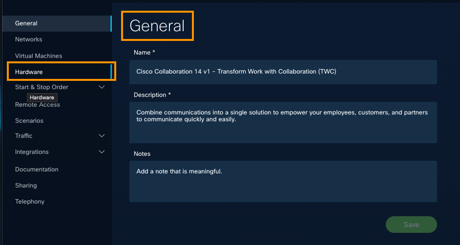
- At top right, click New.
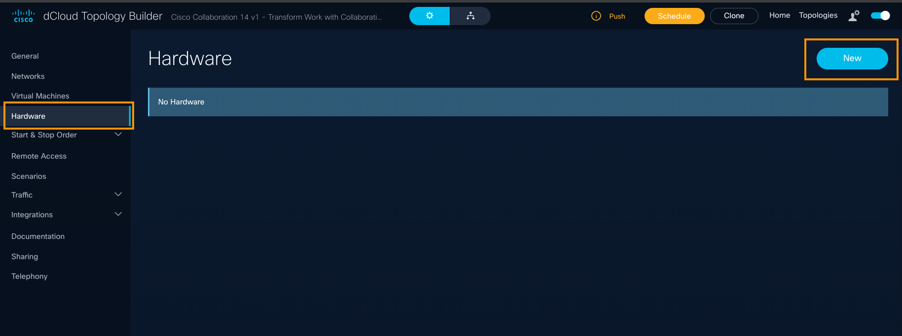
- Select the physical or virtual hardware device you want to add.
You can select an individual device or multiple hardware devices and add them simultaneously.
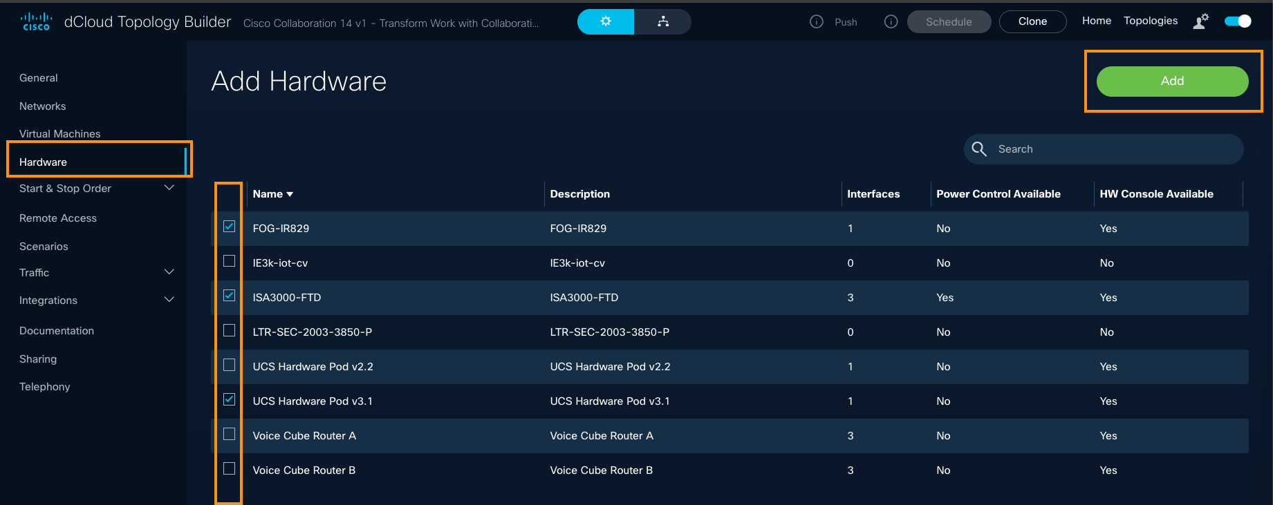
- Now, click the Diagram icon at top, to toggle to this topology's Diagram View and observe that your device(s) are added.
Edit Physical/Virtual Hardware
To edit physical or virtual hardware within a topology, follow these steps.
- At top right, click Topologies.
Optionally, you can go to the Home page and click Get Started.
- On the My Topologies page, click the title or the Pencil icon to open the General configuration page for the topology.
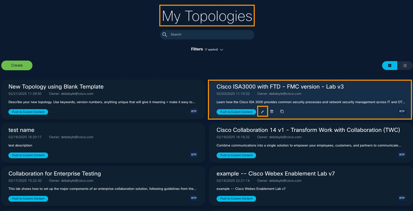
If you do not see the Pencil icon, click any blank space on the page and hover again. - On the left panel of the General configuration page, click Hardware to display the current list of devices assigned to the topology you selected.

- Hover over the device you want to edit, and click the Pencil icon on the right.
If you do not see the Pencil icon, click any blank space on the page and hover again.
Configure VM Start and Stop | Hardware Start order
You can configure the order in which virtual machines are started or stopped, and set the Hardware Start order within a running demonstration, by updating the default settings.
| Order Type | Default Setting | Result |
| VM Start Order | Concurrent | VMs within the topology start at the same time. |
| VM Stop Order | Unordered | VMs within the topology stop at the same time. |
| Hardware Start Order | Unordered | Hardware devices start at the same time. |
Set Hardware Start Order
Default Start Order of Hardware is set to Unordered, which means all virtual machines within a topology start at the same time.
It may be necessary to stop the Virtual Machines (VMs) in a specific order, when a demonstration has ended. You can set the Hardware Start order within a running demonstration, by updating the default settings.
To set the Hardware Start order, follow these steps.
- At top right of any page, click Topologies.
- On the My Topologies page, hover over the topology for which you want to view or configure the Hardware Start order, and click the Pencil icon.
- On the left panel of the VM Start page, select Start & Stop Order, and then click Hardware Start.
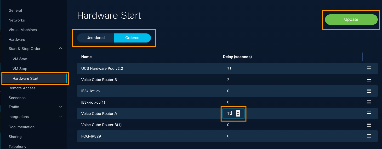
- On the Hardware Start page, you can configure the Hardware Start to be Concurrent or Sequential.
- To move a VM up or down in the ordered list, click the three lines at the right and drag it up or down.
- Click Update.
Delete Hardware
To delete physical or virtual hardware within a topology, follow these steps.
- At top right of a page, click Topologies.
You can always go Home and click Get Started to go to the page.
- On the My Topologies page, hover over the topology from which you want to delete hardware, and click the Pencil icon, to open the General configuration settings page where you can make changes.

- On the left panel, click Hardware to display the list of devices assigned to the topology selected.

- Hover over the hardware device you want to delete, and click theTrash icon to the right.
If you do not see the Trash icon, click any blank space on the page and hover again.

- If you are sure you want to delete this hardware, click Delete.
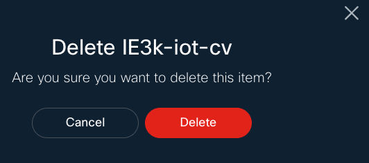
Well done!
You have learned how to manage hardware for your topology. Now, you will explore Remote Access.

 Configure Remote Access
AnyConnect (Secure Client) is enabled by default. You can disable it, if needed. You can enable or disable Endpoint Kits, as well.
Meraki Endpoints and Routers are supported and are recommended.
NOTE: If you simply want to access assets in your topology, you do not need public NAT.
To access assets in your topology: Go to the Remote Access section of Topology Builder and configure browser-based RDP, SSH, and/or console access. Alternatively, you can establish a VPN directly into your vPod using Cisco Secure Client (formerly Cisco AnyConnect) to access assets directly from your own computer.
Enable AnyConnect
When you enable AnyConnect, the user is able to VPN into their dCloud session when they run the demo content.
To configure Remote Access, follow these steps.
- At the top right of any page, click Topologies.
If you're on the Home page, you can click Get Started.
- On the My Topologies page, select the topology for which you want to configure Remote Access.

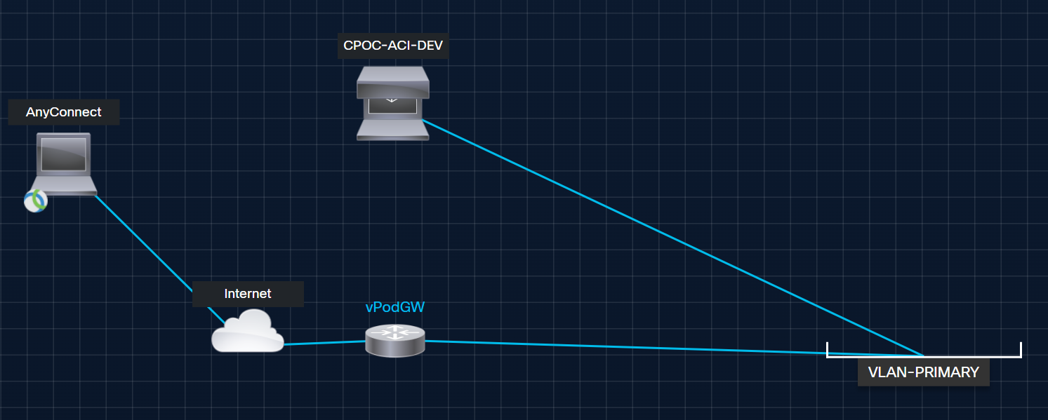
- On left panel of the General configuration page, click Remote Access and verify that the Enable AnyConnect checkbox is checked.
- If Enable AnyConnect is not checked, check it and click Update.

At top of the page, click the button to the right to toggle to the Diagram View.

- Observe that when the AnyConnect feature is enabled, users can connect to dCloud content.
Disable AnyConnect
If you want to disable Cisco AnyConnect remote access to a topology, perform the following steps.
- In the Configuration page of a desired topology, select Remote Access.
- Uncheck the Enable AnyConnect checkbox to clear it.
- To commit your changes, click Update.
Result: When disabled, the Cisco AnyConnect icon is removed in the diagram page for the topology.
Enable Endpoint Kit
Routers manage the network communication among components of an active dCloud session. Routers built into dCloud content automatically start and work as a session becomes active.
You can also use a router that you provide, for some dCloud sessions. Most often, you provide a router to manage connections between an active session and endpoints that you plug into or connect wirelessly to the router, such as your laptop, IP phones, or video conference equipment.
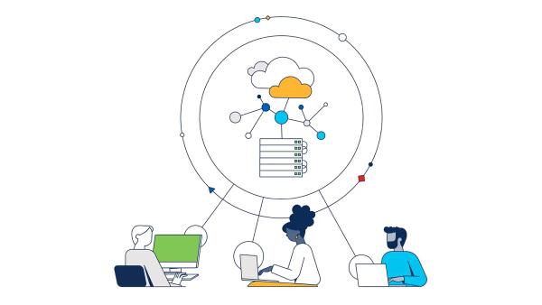
Note: We are updating this topic to provide context about why and how it should be used. We are working on an example and diagram to illustrate a use case for this. Thank you for your patience.
To enable an Endpoint Kit, follow these steps.
- Set up your router for dCloud use.
We recommend you use Meraki endpoints and routers, because they are the preferred and easiest service. For more information, visit dCloud online help.
- For Meraki MX appliances: Add the device for dCloud use only once for each Meraki MX. The Meraki MX configuration will be dynamically added and removed at session start and session end, respectively. The Meraki MX will connect automatically to any session to which you add it.
Connect your laptop to the router using a wired or wireless connection and initiate traffic to the virtual machines in an active dCloud session.
Connect an IP phone, a video conferencing device, or another device to the router's switch ports.
You do not need to perform any additional actions to start the IPSec VPN tunnel that connects the session and Meraki MX. It can take up to 5 minutes after the session becomes active for the VPN tunnel and session/router connection to be fully operational.
The connection automatically initiates when you do one of the following:
Include your configured router and/or Meraki MX in a dCloud session: Select it when you schedule a session and/or add the router and/or MX to an active session.
Share your configured router and/or MX with other dCloud users. Added users can include your router and/or MX in a dCloud session if the router and/or MX is not in use by you or others which whom you shared it.
Because space for user-provided router configurations is limited, legacy routers not used for 6 months are automatically removed from Cisco dCloud. For questions, contact the dCloud team.
Disable Endpoint Kit
To disable the Endpoint Kit remote access to a topology, follow these steps.
- At top right of any page, click Topologies. You can also go Home and click Get Started, if you prefer.

- On the My Topology page, select the topology title or Pencil icon for which you want to disable the Endpoint Kit.
Tip: If the Pencil icon is not displayed, click a blank space on the page and hover over the topology again.

- On the left panel of the General configuration page for the topology, click Remote Access.
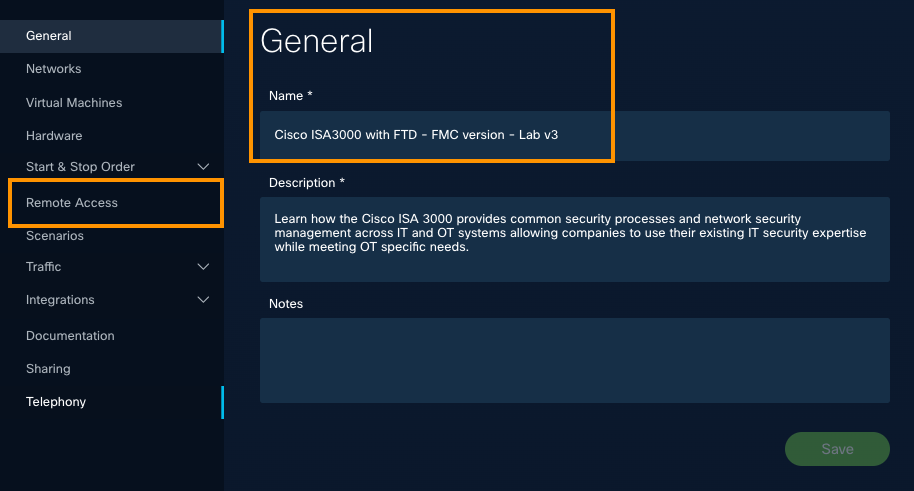
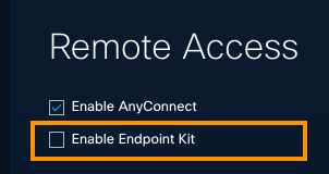
- Verify the Enable Endpoint checkbox is not checked.
Note: If it is checked, check it again to disable the Endpoint Kit, and click Update at top right.
Great job!
You have learned about Remote Access options for your topology. Now, click Traffic to explore more.

Manage Traffic
Topology Builder includes Traffic Features you can use to configure NAT Rules, Inbound Proxy Rules, External DNS record and Mail servers related to your topology.
About NAT Rules
Network address translation (NAT) is used by the dCloud platform in multiple ways to solve different challenges that we will explore in this section. This guide assumes the reader has a basic understanding of networking and network address translation. This guide is not to teach you how NAT works or what it is used for in general, but to help you understand how it is used in the context of the dCloud platform, and what options you have in topology builder for NAT as a content developer. Let’s explore an example topology:
Example Topology - NAT
In the example topology shown here, we have a standard vPodGW, with hosts connected to each of its five (5) directly-connected “inside” interfaces, as well as two (2) web servers --one in dCloud shared services and one on the internet, as well as a web application running on Host A:
This is for illustration purposes only.
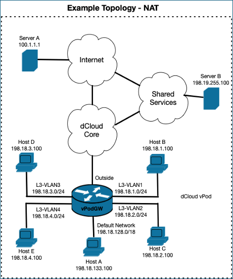
| Network | Host | IP Address |
| Default Network | Host A | 198.18.133.51/18 |
| L3-VLAN1 | Host B | 198.18.1.100/24 and 198.18.1.200/24 |
| L3-VLAN2 | Host C | 198.18.2.100/24 |
| L3-VLAN3 | Host D | 198.18.3.100/24 and 198.18.3.100/24 |
| L3-VLAN4 | Host E | 198.18.4.100/24 |
| Internet | Server A | 100.1.1.1 |
| dCloud Shared Services | Server B | 198.19.255.100/24 |
About Public NAT
When you configure Public NAT in topology builder, you are telling the dCloud platform to dynamically create a static 1:1 NAT rule for a specific asset when a session starts. The asset can be a specific IP address on a specific VM configured in your topology (Public NAT to VM), or any specific IP address of your choosing (Public NAT to IP). When a session starts, an IP address will be selected by the platform from a pool of public IP addresses allocated to the dCloud datacenter your content is running in, and assigned to the asset you configured Public NAT on. The platform will then implement a static NAT rule, which will have the following outcomes:
- Traffic from the VM/IP configured for public NAT destined to the internet will have the source IP address translated to whatever public IP was assigned to your VM/IP by the platform.
- Traffic destined to the public IP address assigned to your VM/IP by the platform will have the destination IP address translated to the real IP address of your VM/IP.
The public IP allocated to your assets by the platform dynamically at session start is random and unpredictable. Every time you start a content session, you are very likely to have a different public IP address assigned to assets configured for public NAT.
Public NAT Notes and Restrictions
- Configuring inbound internet access using public NAT exposes assets in your vPod to the public internet.
- You are responsible for securing assets in your vPod that utilize this feature, and we strongly recommend that you do not use public NAT unless it is absolutely necessary.
Use Case: Outbound Internet Access
By default, every dCloud session provides outbound internet access via the vPodGW. There is nothing special or specific you need to do to make this work in topology builder. From a design perspective, all that is needed is to make sure assets inside your session default route traffic to the vPodGW, and we take care of the rest! With respect to NAT, dCloud automatically accomplishes this by implementing NAT overload (AKA port address translation or PAT) on the vPodGW and on the dCloud edge network. The result is that outbound internet traffic by default will have the source IP address translated to a shared public IP address allocated to whatever dCloud datacenter your session is running in.
For example, if Host A wants to communicate with Server A on the internet, the following happens:
- vPodGW performs a PAT, translating the source IP from 198.18.133.100 à 10.255.x.x, and routes the packet upstream into the dCloud core.
- A NAT device on the dCloud edge will perform a second PAT, translating the source IP address from 10.255.x.x à a public IP address (let’s call it 64.100.12.19 here).
- From Server A’s perspective, it is communicating with 64.100.12.19.
Use Case: Inbound Internet Access
If an asset in your dCloud topology requires inbound access from the public internet, you can configure that in topology builder a few different ways using the public NAT feature. The public NAT feature can be implemented in topology builder two (2) different ways–Public NAT to VM and Public NAT to IP Address–which we will explore here.
Tip: If you simply want to access assets in your topology, you do not need Public NAT. You can achieve this in the Remote Access section of Topology Builder: Configure browser-based RDP, SSH, and/or console access. Or, you can establish a VPN directly into your vPod using Cisco Secure Client (formerly Cisco AnyConnect) to access assets directly from your own computer.
Not all ports and protocols will be allowed inbound from the public internet by default, even with a proper public NAT configuration in topology builder. This is for network security reasons and due to restrictions put in place by Cisco IT. If you need a specific port/protocol open after configuring this feature, please reach out to our support team.
Public NAT Examples
Scroll up a bit to refer back to our Example Topology diagram. In this example, we want both Host A and Host B to be reachable from the public internet via public globally routable IP addresses. For Host A, we want inbound traffic from the internet to be static NAT’d to the IP address assigned to the NIC of Host A, 198.18.133.100. For Host B, we want inbound traffic from the internet to be static NAT’d to an additional loopback IP address assigned on Host B of 198.18.1.200. To accomplish this, we’ll configure Public NAT to VM for Host A, and Public NAT to IP for Host B.
Public NAT to VM Example
Let’s start with Host-A. First, we need to make sure the real IP address we want assigned to the NIC of Host A is configured properly in topology builder. This is required to configure remote access or Public/Internal NAT to VM for this asset. To do this, navigate to Virtual Machines in topology builder, and edit Host-A. Then, expand the Networking section of the VM configuration. Make sure to enter the IP address intended for the NIC of Host A here.
The IP address entered here is only metadata. Entering the IP address in the VM networking configuration will not make any changes to the VM configuration – It is still up to you to configure the correct IP address in the VM’s operating system. Configuring the IP address in topology builder is merely communicating your intent to topology builder, so it can be used as a foundation for other features such as remote access and public/internal NAT.

Now that we have properly laid the foundation, let's configure public NAT to VM for Host A.
To do this, navigate to Traffic > NAT Rules in Topology Builder and configure as follows:
- Type: Public NAT to VM.
- Target: Host-A <-- Host-A must already be added to your topology at this point.
- IP Address: 198.18.133.100 (The IP you configured earlier for the VM settings).
- Leave East/West NAT unchecked. This feature will be discussed in a later example.
- Click Add.

Public NAT to IP Example
Next, we will set up Host-B for Public NAT to IP. The only difference with Public NAT to IP is that the target IP address is not already pre-defined in Topology Builder under the VM networking configuration, as this value of whatever you need it to be.
In this example, this IP is the loopback address we will have configured on Host-B that is not visible in Topology builder. This really can be whatever your specific use case requires.
To set up Host B, navigate to Traffic > NAT Rules, and configure as follows.
- Type: Public NAT to IP.
- Target: Host-B Loopback (This is an arbitrary name for this rule and can be anything).
- IP Address: 198.18.1.200 (Loopback IP address of Host B).
- Leave East/West NAT unchecked. This feature will be discussed in a later example.
- Click Add.

Public NAT Example Outcomes
When you have properly configured everything, we expect the following outcomes for this example:
- When a session is started, the platform will allocate a Public IP address for Host-A, and a Public IP address for Host-B. For this example, let’s say you spun up a session, and the platform allocated 64.100.12.100 for Host-A, and 64.100.12.200 for Host-B.
- Outbound traffic
- Traffic sourced from Host A’s NIC (198.18.133.100) destined to the internet will have the source translated to 64.100.12.100.
- Traffic sourced from Host B’s loopback (198.18.1.200) destined to the internet will have the source translated to 64.100.12.200.
- All other outbound traffic from other vPod assets will be overloaded / PAT as normal.
- Inbound traffic
- Traffic sourced from the internet and destined to 64.100.12.200 will have the destination translated to Host B’s loopback IP 198.18.1.200.
About East/West NAT
When you configure Public NAT, there may sometimes be a requirement to access an asset inside the vPod using that asset’s public FQDN (Fully Qualified Domain Name) / IP Address from another asset which is also inside the vPod.
The dCloud platform supports this type of traffic flow, using a feature we call East/West NAT. It is very similar in concept to what you may have seen referred to as "NAT loopback" or "NAT hairpinning" in other products, with a few notable restrictions.
East/West NAT Restrictions and Requirements
- East/West NAT is used in conjunction with the Public NAT feature.
- This functionality is somewhat limited in that the source must be on the default network. The target can be on any VLAN, except the default VLAN.
- The asset receiving East/West NAT configuration in Topology Builder is the Destination / Target Device.
Use Case: Intra vPod communication to external IP (East/West NAT)
As mentioned, when you configure Public NAT, there may sometimes be a requirement to access an asset inside the vPod using that asset’s public FQDN (Fully Qualified Domain Name) / IP Address from another asset which is also inside the vPod.
Become familiar with the NAT Restrictions and Requirements above.
Let's refer back to our Example Topology Diagram.

In this use case/example, we want Host-C to be reachable from the public internet via a public, globally-routable IP. Additionally, Host A needs to communicate with Host C using Host C’s internal IP of 198.18.2.100.
To achieve the desired outcome, we will configure Host-C for Public NAT to VM, in the same way that we configured Public NAT to VM in the previous example, but we will add the additional step of checking the East/West NAT box in the NAT rule configuration of Topology Builder.
The East/West NAT checkbox makes it possible for hosts on other VLANs (such as Host-A) to communicate with Host-C, using Host-C’s internal IP address.

East/West NAT example outcomes
When you have properly configured everything, we expect the following outcomes for this example:
- When a session is started, the platform will allocate a public IP address for Host C. For sake of this example, let’s say you spun up a session, and the platform allocated 64.100.12.100 for Host C.
- Host A to Host C traffic
- Traffic sourced from Host-A’s NIC (198.18.133.100) destined to Host-C’s public IP address of 64.100.12.100 will be “hairpinned” and have the destination IP translated to 198.18.2.100, then be routed to Host C. This allows Host A to communicate with Host-C ceven if Host A resolves Host-C’s FQDN to Host C’s public IP address.
- Inbound traffic
- Traffic sourced from the internet and destined to 64.100.12.100 will have the destination translated to Host-C’s NIC IP 198.18.2.100 and routed to Host-C.
About Internal NAT
When you configure Internal NAT in Topology Builder, you are telling the dCloud platform to dynamically create a static 1:1 NAT rule for a specific asset when a session starts. The asset can be a specific IP address on a specific VM configured in your topology (Internal NAT to VM), or any specific IP address of your choosing (Internal NAT to IP). When a session starts, an IP address will be selected by the platform from a pool of IP addresses from the reserved 100.64.0.0/10 prefix, and assigned to the asset on which you configured Internal NAT.
The platform will then implement a static NAT rule, which will have the following outcomes:
- Traffic from the VM/IP configured for Internal NAT destined to shared services will have the source IP address translated to whatever IP was assigned to your VM/IP by the platform from the 100.64.0.0/10 address space.
- Traffic destined to the IP address assigned to your VM/IP by the platform from the 100.64.0.0/10 address space will have the destination IP address translated to the real IP address of your VM/IP.
The IP allocated to your assets by the platform dynamically at session start is random and unpredictable. Every time you start a session of your content, you are very likely to have a different IP address assigned to assets configured for public NAT.
Use Case: Inbound Shared Services Access
Every dCloud datacenter has networks collectively known as shared services. Shared services are a dedicated, static set of networks that exist outside the vPod that typically contain assets that need to be shared and accessible from any dCloud session. For example, maybe there is a demo that requires all sessions of the content to access a shared common active directory or DHCP server. Instead of replicating those assets across every session of that content, we could place a single AD or DHCP server into shared services, and those assets would be available from inside any dCloud session in that datacenter.
Currently, the ability to place assets into dCloud shared services is reserved for developers within the GDE / dCloud team. You cannot add assets to shared services on your own. If you require this functionality, please work with the dCloud team.
By default, vPod assets can access shared services by way of a NAT overload (PAT) with no additional configuration. However, this can be limiting because this means assets in the vPod can initiate communication with shared services, but assets in shared services cannot initiate communication to assets in the vPod. This limitation exists due to the nature of how PAT functions.
A use case exists where you may require assets in shared services to be able to initiate communication to assets inside a dCloud session. This use case is very similar to the inbound internet access use case, and dCloud has similar features to support it.
As we saw in a previous example, we utilize the Public NAT features in topology builder (Public NAT to VM or Public NAT to IP) for the inbound internet access use case. Similarly, to support this use case we will use the Internal NAT features in topology builder (Internal NAT to VM or Internal NAT to IP). Fundamentally, Public NAT and Internal NAT features work the same way. The only difference is that with Public NAT, we are doing a static 1:1 NAT with public routable IP addresses, and with Internal NAT we are doing a static 1:1 NAT using a reserved shared IPv4 address space (100.64.0.0/10).
Internal NAT Examples
Let's again refer to our Example Topology Diagram.

In this example, we want both Host-C and Host-D to be reachable from Server-B which is located in dCloud Shared Services.
For Host-C, we want inbound traffic from shared services to be static-NAT’d to the IP address assigned to the Network Interface Card (NIC) of Host-C, 198.18.2.100.
For Host-D, we want inbound traffic from shared services to be static-NAT’d to an additional loopback IP address assigned on-Host D: 198.18.3.200. To accomplish this, we’ll configure Internal NAT to VM for Host-C, and Internal NAT to IP for Host-D.
Internal NAT to VM Example
We will start with Host-C. First, we need to make sure the real IP address we want assigned to the NIC of Host C is configured properly in topology builder. This is required to configure remote access or Public/Internal NAT to VM for this asset. To do this, navigate to Virtual Machines in topology builder, and edit Host-C. Then, expand the Networking section of the VM configuration. Make sure to enter the IP address intended for the NIC of Host C here.
Important Note
The IP address entered here is only metadata. Entering the IP address in the VM networking configuration will not make any changes whatsoever to the VM configuration – It is still up to you to configure the correct IP address in the VM’s operating system. Configuring the IP address in topology builder is merely communicating your intent to topology builder, so it can be used as a foundation for other features such as remote access and public/internal NAT.

Now that we have properly laid the foundation, let’s configure Internal NAT to VM for Host C. To do this, navigate to Traffic > NAT Rules and configure as follows.
- Type: Internal NAT to VM.
- Target: Host-C (Host-C must already be added to your topology at this point).
- IP Address: 198.18.2.100 (The IP you configured earlier for the VM settings).
- Leave East/West NAT unchecked.
- Click Add.

- Type: Internal NAT to IP.
- Target: Host-D Loopback <-- This is an arbitrary name for this rule and can be anything.
- IP Address: 198.18.3.200 <-- Loopback IP address of Host D.
- Leave East/West NAT unchecked.
- Click Add.
- When a session is started, the platform will allocate an IP addresses from the 100.64.0.0/10 prefix for Host C, and Host D. For sake of this example, let’s say you spun up a session, and the platform allocated 100.108.1.100 for Host C, and 100.108.1.200 for Host D.
- Outbound traffic to shared services
- Inbound traffic from shared services

Example: Internal NAT to IP
Next, we will set up Host-D for Internal NAT to IP. The only difference with Internal NAT to IP is that the target IP address is not already pre-defined in topology builder under the VM networking configuration, as this value is whatever need it to be. In this example, this IP is the loopback address we will have configured on Host-D that is not visible in topology builder. It can really be whatever you need for your specific use case.
To set up Host D, navigate to Traffic à NAT Rules in topology builder, and configure as follows.

Internal NAT example outcomes
When you have properly configured everything, we expect the following outcomes for this example:
o Traffic sourced from Host C’s NIC (198.18.2.100) destined to Server B will have the source translated to 100.108.1.100
o Traffic sourced from Host D’s loopback (198.18.3.200) destined to Server B will have the source translated to 100.108.1.200.
o All other outbound traffic from other vPod assets will be overloaded / PAT as normal.
o Traffic sourced from Server B in shared services and destined to 100.108.1.100 will have the destination translated to 198.18.2.100.
o Traffic sourced from Server B in shared services and destined to 100.108.1.200 will have the destination translated to 198.18.3.200.
Configure Inbound Proxy Rules
This is an HA Proxy solution to save on public address uses and proxy traffic into Topologies without using 1:1 NAT’ing. This feature enables you to expose a web server externally without using a public IP address.
When you configure Inbound Proxy Rules in Topology Builder, you are telling the dCloud platform to dynamically create a static 1:1 PAT rule for a specific asset when a session starts. The asset a specific IP address on a specific VM configured in your topology (Inbound Proxy Rules). This feature is ideal for users wanting to expose a web based application to the internet. In addition to selecting a specific target and IP address, the user needs to specify a TCP port that the application listens on, check the box if the application use SSL or not, specify a URL Path, check the Show Hyperlink box, and specify a Hyperlink Text. The URL Path can be “/” or a more specific path. The Hyperlink Text, is the hyperlink name that will be displayed in TBv3 dCloud Session View.
When a session starts, an IP address will be selected by the platform from a pool of RFC 1918 IP addresses allocated to the dCloud datacenter your content is running in, and assigned to the asset you configured Inbound Proxy Rules on. The platform will assign a URL using a combination of the VM name, numbers, and the domain assigned to the dCloud datacenter. The platform will create a DNS record for the URL pointing to a platform reverse proxy server. Accessing the hyperlink is limited to the TBv3 session page. The platform will then implement a static NAT rule, which will have the following outcomes:
- Traffic from the VM/IP configured for Inbound Proxy Rules destined to the internet will use PAT, same as in the Outbound Internet Access use case.
- Traffic destined to the URL (VM/ IP) address assigned to your VM/IP by the platform will have the destination IP address translated to the real IP address of your VM/IP. Traffic from the internet will be first forwarded to the reverse proxy server, then forwarded to the vPod using the 1918 IP addresses allocated.
When you name a VM that will be used with this feature, the VM name will become part of the URL. Recommended: Use only lowercase, no special characters (!, $, &, etc.), and no spaces. The VM name may contain letters (a-z) and hypens(-).
Examples: Inbound Proxy Rules
Scroll up a bit and refer back to our Example NAT Topology illustration (above). In this example, we want an application on Host A to be reachable from the public internet via URL that is only accessible by users who have authenticated to the demo session, and has access the URL directly from with the TBv3 demo session. For Host A, we want inbound traffic from the internet to the application to have an Inbound Proxy Rule to the IP address assigned to the NIC of Host A, 198.18.133.51. To accomplish this, we’ll configure Inbound Proxy Rules to VM for Host A, the IP address of Host A (198.18.133.51), the TCP port the application is listening on (443), check the SSL check box, enter a backslash (/) in the text box for URL Path, check the checkbox for Show Hyperlink, and specific a display name for the Hyperlink Text field.


At session start the Hyperlink (myweb : https://centos-7-server-80gb-preconfig-XXXXXXXXXX.px.dc-0X.com/) to access the application can be found using the Info tab at the top of TBv3 dCloud Session View -> Info -> Public NAT IP / Internal NAT IP / Proxy
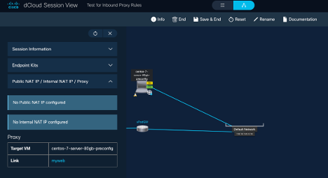
Great job!
You have explored Traffic. Now, click Push to dCloud to explore more advanced configurations you can perform on your topology.

Push Functionality: Quick Reference
The table below summarizes the key actions involved in pushing your topology content to dCloud. It provides an overview of each step, its description, and important notes to help ensure your topologies are properly synchronized and ready for scheduling.
| Action | Description | Notes |
| Configure topology | Complete your topology configuration before pushing it to dCloud. | |
| Push Content | Activate the Push function to send your topology to dCloud. | Content cannot be scheduled or launched until pushed. |
| Status Change | After pushing, status changes to In Sync with dCloud. | This status remains until further changes are made. |
| Edit Topology | Editing a topology with In Sync status changes the status, requiring another push. | |
| Clone Topology | Cloning an In Sync topology results in a clone also In Sync until edited. | |
| Push Option Location | The Push option is located at the top of the General or other configuration pages. | |
| View Status | Check the topology status on the My Topologies page. | In Sync status = ready to schedule. |
| Schedule Session | Sessions can be scheduled directly from Topology Builder. | My Topologies page, General (config) page |
| Availability in dCloud | Content appears in dCloud under My Hub > Custom content when the status is In Sync. |
Push to dCloud: Procedure
1. At top right of any page, select Topologies.
2. Verify the My Topologies page is toggled to the Detailed View (on the right).

3. Check Topology Status to be sure the topology is In Sync with dCloud.
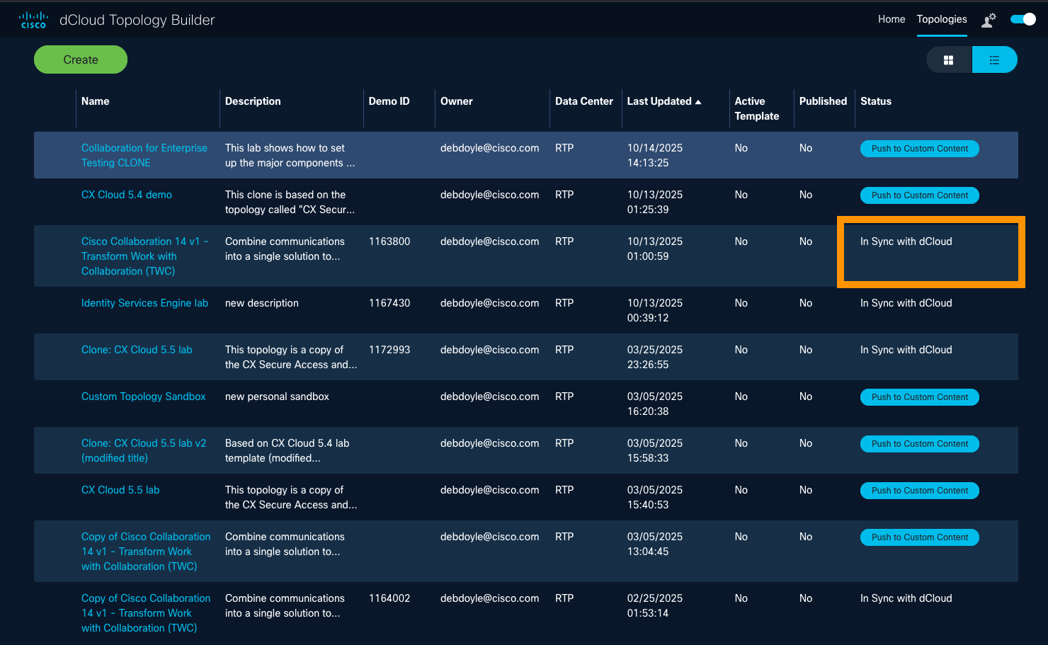
4a. On the My Topologies page, click Push to Custom Content to send the content, then click Save at the prompt.
OR
4b. Open the topology, which displays the General configuration page by default, then click the Push button at the top and click Save when prompted.
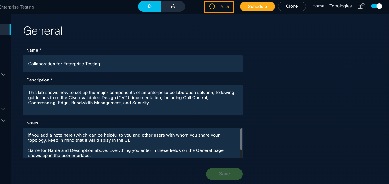
Push to Custom Content in dCloud - Prompt
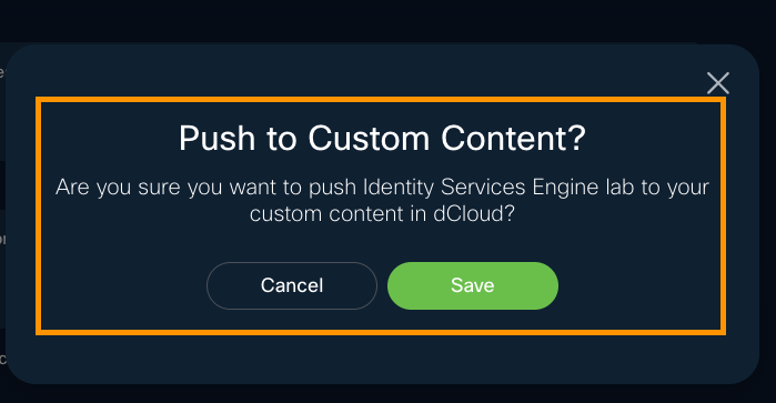
This process usually completes within seconds.
5. To schedule a dCloud session:
- Click the topology title to open its General settings page.
- At the top of the General page or any configuration page, click Schedule.
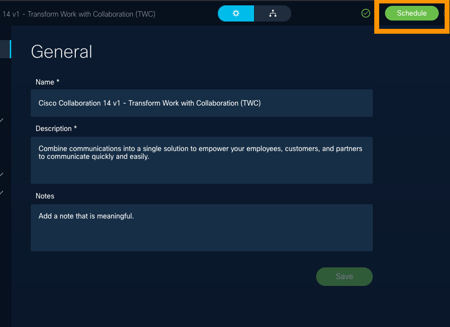
Result:
Once pushed, the topology status changes to In Sync with dCloud, and the content becomes available within dCloud under My Hub > Custom content, ready to schedule and run.
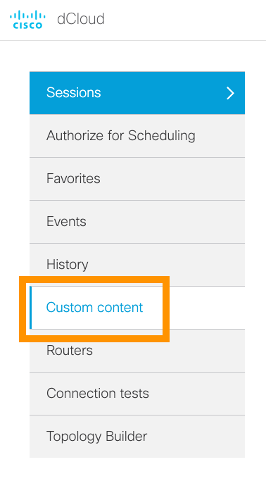
New! Launch Panel for scheduled content with IDAC-hosted recipes
Demo developers can now enable the Launch panel for scheduled content with IDAC-hosted recipes. This feature allows users to access IDAC splash pages directly from the Session View page (renamed "Launch Panel"), eliminating the need to navigate through jump hosts.
This enhancement reduces complexity and helps you weave a cohesive story across Cisco and third-party applications without the hassle of managing URLs or credentials.
To get started: Download and Watch Quick Video Demo.

- Open the My Topologies page and select a topology.
- On the General tab, check Enable launch panel.
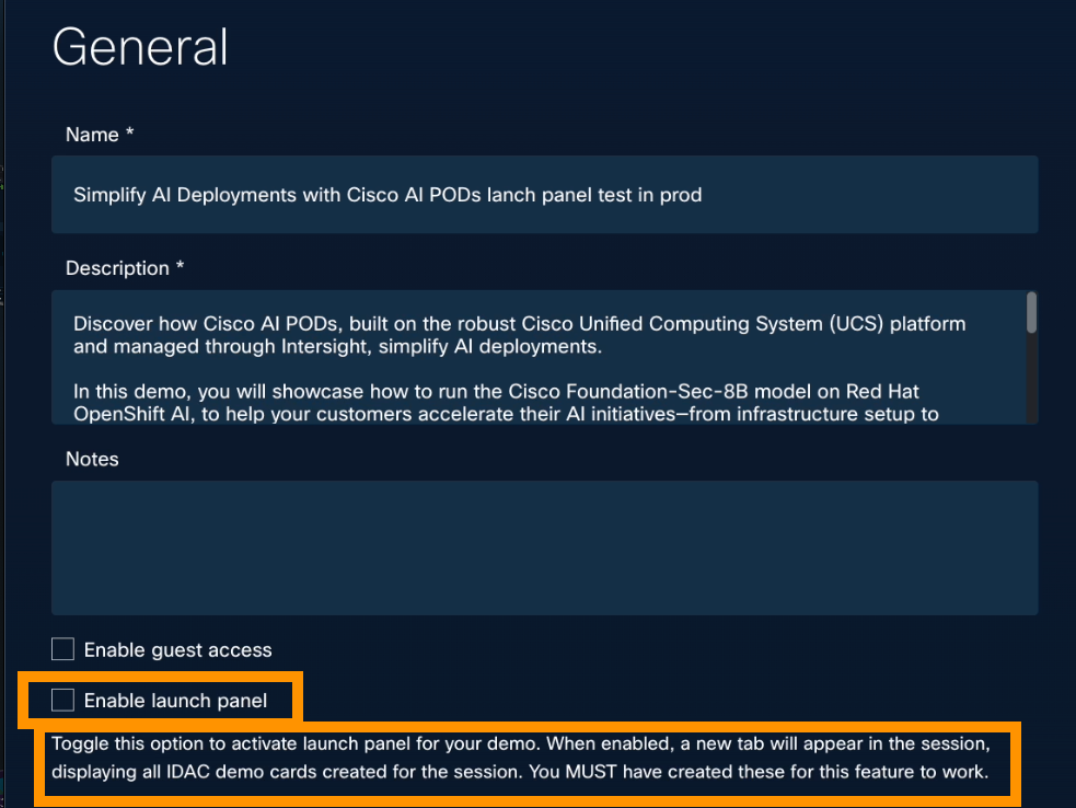
Promote Custom Content
Content created in Topology Builder can be promoted by a demo developer for use in events or for publishing content in the dCloud content catalog.
Promoted content means that dCloud ensures your new demo is spread across storage nodes so the demo sessions will not be isolated and a single node does not have to carry all the weight.
Make Promoted Content updates to the Promoted Topology, rather than the original topology created.
When your custom content has been successfully promoted, a copy of your topology is made, and a status flag is displayed in Topology Builder to indicate that this content is promoted, and a new Demo ID is provided.
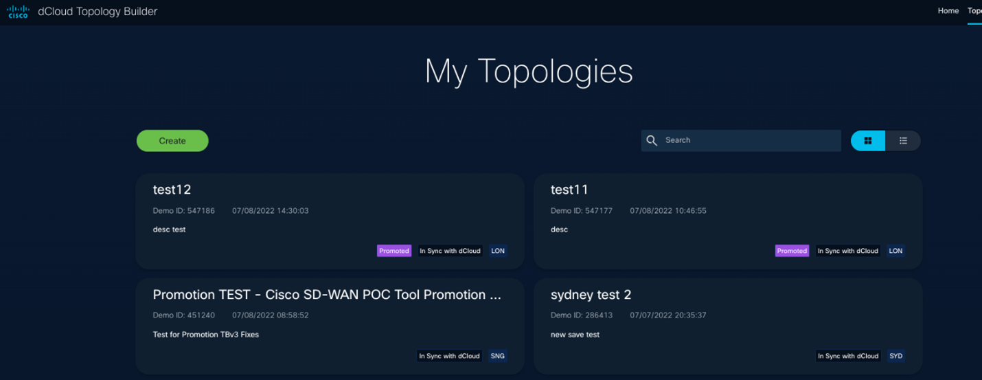
Run Custom Content
After the topologies are pushed to custom content, you can schedule a session like any other dCloud catalog content, if there is enough capacity in that Data Center. You can even schedule your session from the Topology Builder app.
Example
- On any page where you can edit your topology, you can click Schedule to launch / run it in dCloud, if it is prepared to Push to dCloud (or has already been pushed).
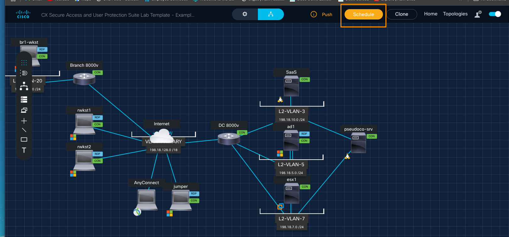
- If you have not yet pushed the content to dCloud, you will be prompted to do so before you can schedule your session.
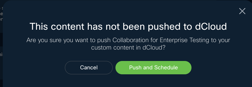
- In this example, let's select Push and Schedule Content, to see the Schedule Session calendar quickly display.
dCloud Session Scheduler
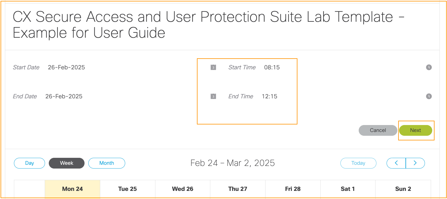
Great job!
You have gone through all the steps, from creating your topology to pushing it to dCloud. Congratulations!
Even if you have used some Advanced Features in the Topology Builder app., we recommend that you select the Advanced tab (next in the menu) and quickly review that section.
Also, keep your eye on What's New in the Get Started menu, because you will instantly learn about new features and more in the release notes.

Advanced Configuration
Explore advanced features and their potential uses for your topologies. You will discover possibilities and get your own great ideas about trying out something new.
Licensing for Topology Builder is internally managed by the dCloud team and not related to software or hardware licensing but used to control the volume of sessions running on Topology Builder.
Access VMs via SSH - Advanced
There are two ways to access VMs via SSH in your dCloud builds, without needing to use a public IP address.
- Enable SSH on the VM in topology builder - This allows you SSH access via your web browser from Session View.
- Use Secure Client (AnyConnect) to VPN from your machine to your dCloud session. Topology Builder enables AnyConnect by default; when connected, you can use any SSH client you like to connect to a VM.
If you need access from the public internet, you can configure NAT on the VM to which you need access. However, we recommend doing this only if absolutely necessary, due to security reasons.
In any of these cases, please note that it is your responsibility to make sure SSH is configured/enabled properly on the dCloud virtual machine and that routing inside your vPod is properly set up.
Configure Scenarios - Advanced
Empower dCloud users to choose which scenario they'd like to experience in which order. This feature enables a quality user experience in less time than it takes to watch the demo from start to finish.

Review the Enabling and Configuring Scenarios topics that follow. Then, learn potential uses for the Scenarios feature.
Enable Scenarios
Scenarios, when enabled in your Topology, configured in your Virtual Machine, and pushed to dCloud custom content, are available to select upon scheduling from dCloud. This topic explains how to enable Scenarios. The topic following this one describes how to configure them within a VM.
Configure Scenarios within a Virtual Machine
Now that you have enabled Scenarios, you can configure them within a Virtual Machine. To do this, you need to run the Topology you’ve created on dCloud and configure the scenarios with a custom-created script.
In this example, you will create two scenarios using a simple PowerShell script that defines to which site Chrome goes each time you log on to the Windows VM RDP connection. This is based on the Scenario selected by the user who is launching the dCloud session.
Scenarios do not work on Hardware devices. If you need guidance on how to configure in Linux, please reach out to our dCloud Topology Builder Community.
Scenarios: Current and Potential Uses
Currently, there is a dCloud lab that parses the scenario and executes in-demo automation based on user selection. To see this in action, visit Cisco IOS XR Enablement - Multilab Sandbox v1. Additional Uses for Scheduled Tasks are in progress and will be added soon.
Following are some potential uses for the Topology Builder Scenario functionality:
Multi-day Labs: A lab can require multiple configurations, such as day 1 config, day 2 config, and so on and so forth. Each day can be configured to include a specific scenario, and the automation can trigger/configure the baseline per the user's selection by parsing the session.xml file.
A and B Testing: Testing between lab configurations is like Multi-day Labs (above) but illustrates an A configuration vs. a B configuration, based on the user's selection by parsing the session.xml file.
CML Use in Walk-In, Self-Paced Labs: While CML has five labs currently registered, a single, specific lab can auto-launch based on a user's selection by parsing the session.xml file.
Build a Topology with Terraform - Advanced
The first release of the dCloud Terraform Provider, in the Cisco Open Source Repository and the public Terraform registry, enables you to create dCloud topologies using the Terraform CLI, the industry-standard Infrastructure-as-code tool.
Build a Topology with Terraform CLI
The initial release supports networks, virtual machines, and hardware. Coming soon: Full support for all other dCloud resource types.
You can build your topology with the Terraform command-line Interface (CLI), rather than the Topology Builder graphical user interface (GUI).
Watch the Terraform Provider Walkthrough.
- Go to https://registry.terraform.io/providers/cisco-open/dcloud/.

To locate your TB_AUTH_TOKEN, see Local Storage in your browser.

Join the dCloud Topology Builder Community to ask questions and get support.
IPV6 Quick Start - Advanced
Explore IPv6
To discover why demand for IPv6-based connectivity continues to grow world-wide, we recomment that you review the IPv6 Quick Start Demo profile and schedule a demo session.
To learn to deploy IPv6 in a Cisco dCloud vPod "The Easy Way or The Manual Way," follow along with the dCloud IPv6 Quick Start Guide.
Schedule your demo session and experiment with IPv6 Topology.
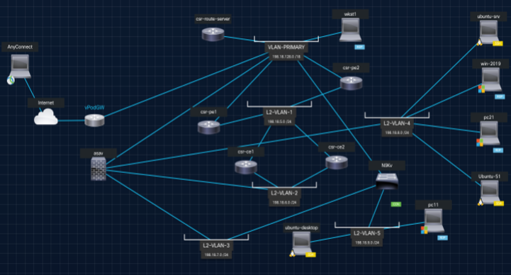
Watch IPv6 Videos
About vPodGW6
Consider vPodGW6 a dCloud platform-supported device, as well as a template that you can add to your topology (like any other template). When added to your dCloud topology, in conjunction with the required automation, the vPodGW6 router automatically provides these services to your vPod:
- Public IPv6 prefixes and outbound IPv6 internet access on all interfaces.
- Advertisement of IPv6 Cisco Umbrella DNS servers on all interfaces.
- Dynamic routing via OSPFv3 on all interfaces.
- Inter-VLAN routing between default/VLAN-PRIMARY and all dCloud L3-VLANs, for:
-Global Unicast Address (GUA) prefixes which are dynamically allocated per session.
-Unique Local Address (ULA) prefixes which are static; they do not change.
Customize your topology with Cisco Modeling Labs (CML) - Advanced
As a dCloud content developer, it is best practice to run Cisco Modeling Labs with dCloud Topology Builder.
For example, review the CML - Catalyst SD-WAN 20.15 Lab: Custom Topologies demo to see the flexibility and support capabilities.
This content is in progress. Thank you for your patience.
What's Next
Your GSE Demo Team is here to support you, by empowering you to partner with us in developing demos, labs, and sandboxes that enable sales. Topology Builder is an app we created for you to bring more flexibility and efficiency so you have more time to create exceptional client experience.
Got an idea for a new feature we might add to enhance Topology Builder? We're listening! Share your idea for a Feature or Feature Enhancement through this brief form or click Request a Feature from the Topology Builder Home page.
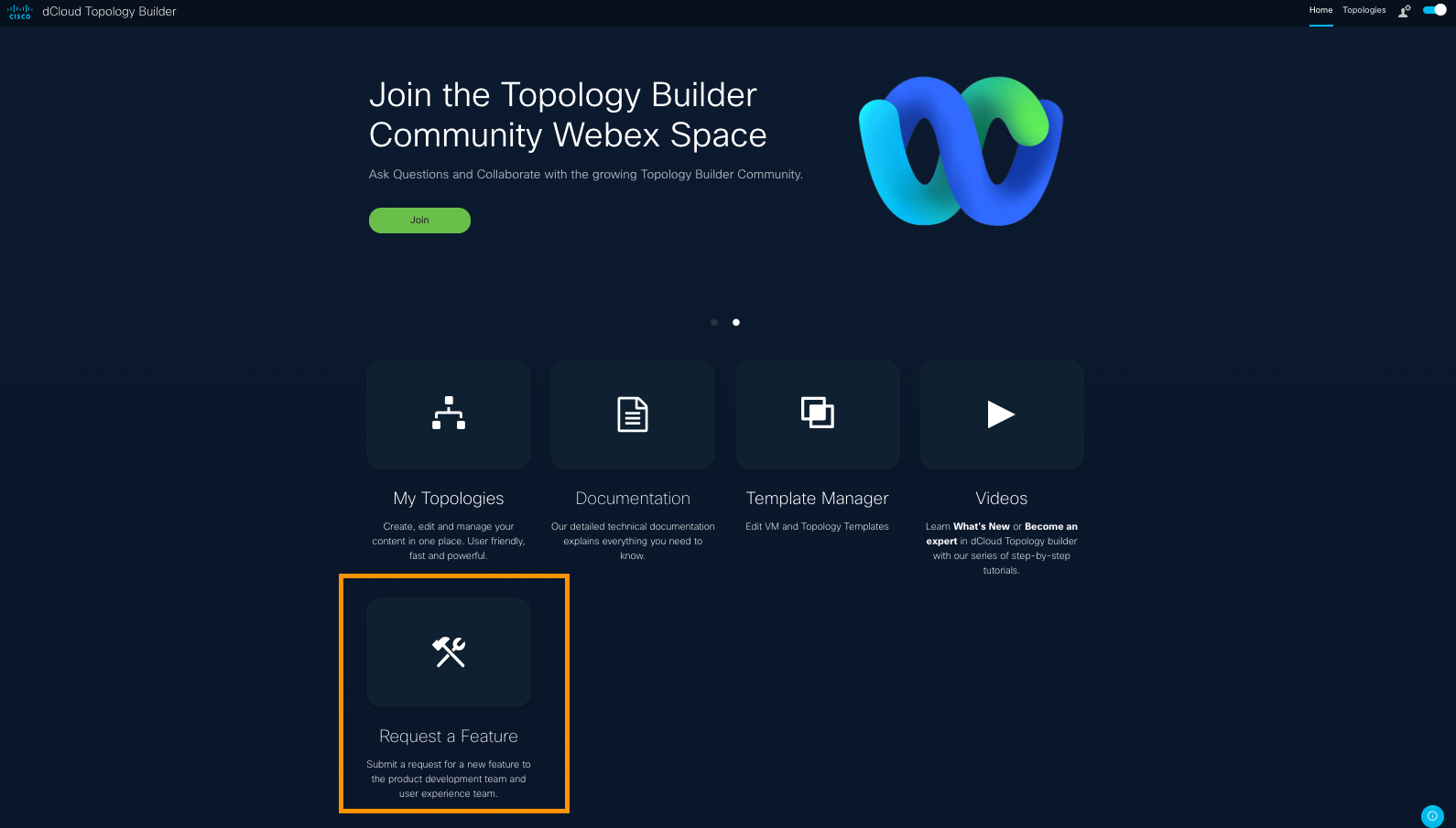
If you haven't already joined, you might consider becoming part of our active online community. It's a great place to ask questions, confer with experts, and observe and learn.
Please do click the small, vertical, blue Give Feedback banner on the right and keep in touch with us!
- SaaS & Cloud
- ThousandEyes
- DUO
- Cisco Secure Endpoint (AMP)
- Umbrella
About SaaS Integrations
SaaS integrations enable your topology to connect and interact with various cloud-based software services, enhancing visibility, security, and operational efficiency. Thanks to the seamless integration between Topology Builder and the in-Demo Automation Controller (iDAC), you can effortlessly provision these accounts and enable auto-login capabilities for users, streamlining your demo experience.
Drive Customer Business Value
By leveraging SaaS applications such as Webex, ThousandEyes, AppDynamics, and Cisco Secure Endpoint, you can drive customer business value through centralized management, real-time monitoring, threat intelligence, and collaboration tools. These integrations improve network performance, security posture, and user experience.
Enhance your demos with integrated SaaS and cloud services to accelerate setup, simplify access, and deliver compelling, real-world scenarios that resonate with your customers. Showcase Cisco’s comprehensive ecosystem to boost your sales pitch and save time by managing integrations directly within your topology for faster, more impactful demonstrations.
Public Cloud support currently includes Amazon Web Services and is available exclusively to dCloud content developers.
Add SaaS Integrations to Your Topology
- In Topology Builder, navigate to Integrations > SaaS on the left panel.
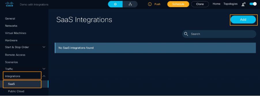
- Click Add to select the integration(s) you want to integrate into your topology.

- Provide the Integration Name and any product-specific parameters.
- Click Save.
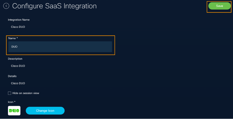
- Each integration has unique configuration parameters depending on the SaaS product and account provisioning method.
- Once added, your SaaS integrations appear under Integrations > SaaS, with management options (Edit/Delete) available on the right.
5. Click Add to select the integrations you want to integrate into your topology.


Navigate and Manage Your Integrations in the Session View
When a dCloud session is active, open the dCloud Session View and go to the SaaS tab. All available integrations are listed on the left panel. Integration names reflect what you defined in Topology Builder when adding them.
Expand any integration to view additional details such as account names, usernames, and action buttons like Activate or Login. These attributes vary by SaaS product. For more details, refer to the specific SaaS integration examples that follow.
Integration tab names in the left panel (DUO, ThousandEyes, etc.) are defined by the content creator in Topology Builder, so your screen may look slightly different in other topologies.
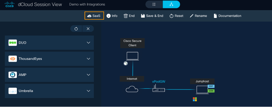
SaaS Integrations Summary Table
| Integration | Custom Parameters | Account Provisioning | Auto-login Available | MFA Required | Session View Actions |
| ThousandEyes | Account Group Name, User Role ID | Account Group created or reused per session | Yes | No | Expand SaaS tab > ThousandEyes > Go to account |
| Cisco DUO | None | New DUO account with dynamic email | No | Yes | Expand SaaS tab > DUO > Activate Account, then Log in |
| Cisco Secure Endpoint | None | New account created | Yes | No | Expand SaaS tab > AMP > Go to account |
| Cisco Umbrella | None | Pre-created Org assigned per session | Yes | No | Expand SaaS tab > Umbrella > Go to account |
Depending upon on the specific SaaS product, the user experience with provisioning and using SaaS accounts may be different.
For examples of the current SaaS integrations in Topology Builder, continue with the tabs on the Configure SaaS Integrations menu above.
Drive Business Value with ThousandEyes Integration
Configure ThousandEyes integration to gain comprehensive network and application performance insights. This integration enables proactive monitoring, rapid issue detection, and improved user experience. Key customer business outcomes include:
- Enhanced network visibility across hybrid environments
- Faster troubleshooting and reduced downtime
- Improved customer satisfaction through reliable service delivery
Configure ThousandEyes Integration
When using ThousandEyes integration in your topology, a ThousandEyes Account Group is provisioned under the global “Cisco Demo dCloud” organization.
1. Designate and/or modify input parameters for ThousandEyes.
- Account Group Name
- If an account group with the given name exists in “Cisco Demo dCloud” organization, a new user auto-login is generated for the session duration.. After the session stops, ThousandEyes agents, tests, reports will be deleted.
- If an account group with the given name does not exist in “Cisco Demo dCloud” organization, it is created at the dCloud session start and deleted after the session is terminated.
- Default value: dcloud-$requestId$ (the $requestId$ variable is unique for every dCloud session; it enables you to create unique Account Groups per each dCloud session).
- User Role ID
- Defines the access permissions within the ThousandEyes Admin portal.
- Default: 4108321 (“TB-user-default”) grants full admin permissions within the Account Group.
![]()
2. Under dCloud Session View, open the SaaS tab and expand the ThousandEyes tab on the left panel.
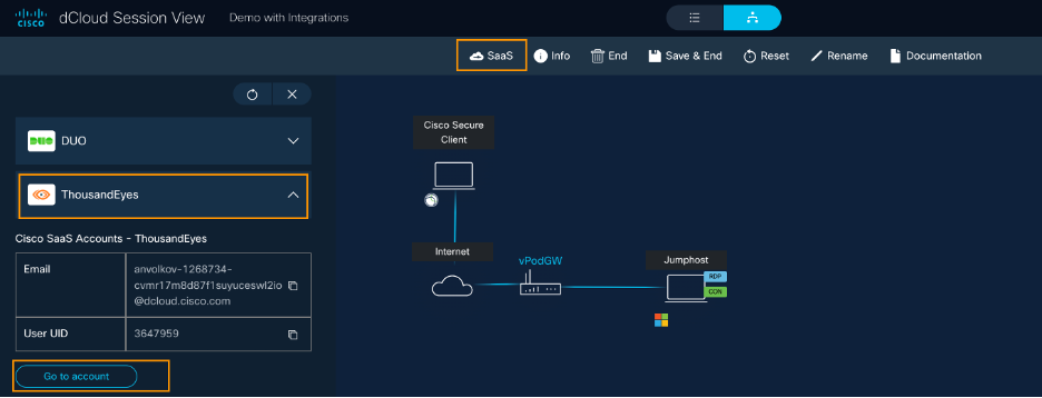
2a. Log in to the ThousandEyes Admin portal: Click the Go to Account button in the left panel.
If you experience any login issues with integrations, try using a Private (or Incognito) browser window.
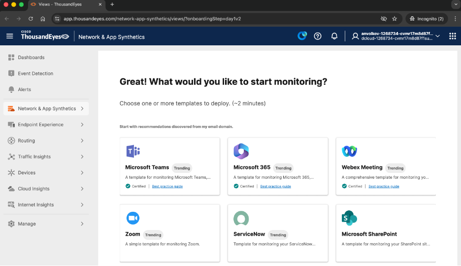
Drive Business Value with DUO Integration
Set up Duo integration to enforce strong multi-factor authentication (MFA) and secure access across your network. This integration supports zero-trust security models and reduces risk of unauthorized access. Key customer business outcomes include:
- Increased protection against credential theft
- Simplified user access management
- Compliance with security policies and regulations
Configure Cisco DUO Integration
When integrating DUO into your topology, a new DUO account will be created for you. It will use a dynamically generated email address to log in. Because DUO requires a multi-factor authentication (MFA) to be setup, we do not provide automatic login capabilities for DUO account. Every user will have to set up their password and MFA in their corresponding dCloud session.
DUO Integration does not have any custom parameters for you to configure.
1. Open the Edit SaaS Integration page for Cisco DUO.
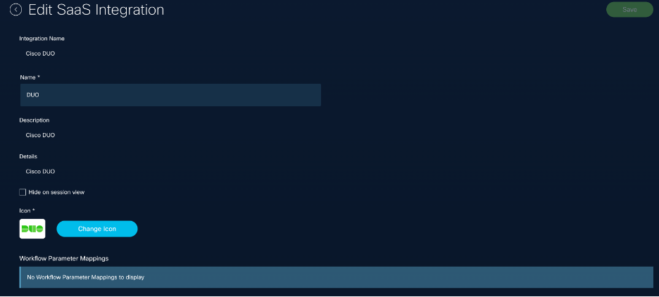
2. Under dCloud Session View, open the SaaS tab and expand the DUO tab on the left panel.
As part of the demo flow, every user has to activate and set up their DUO account manually. You can see an email address that must be used for the user login, and the suggested password. You can set up any other password for your account, but you must use the provided email address.
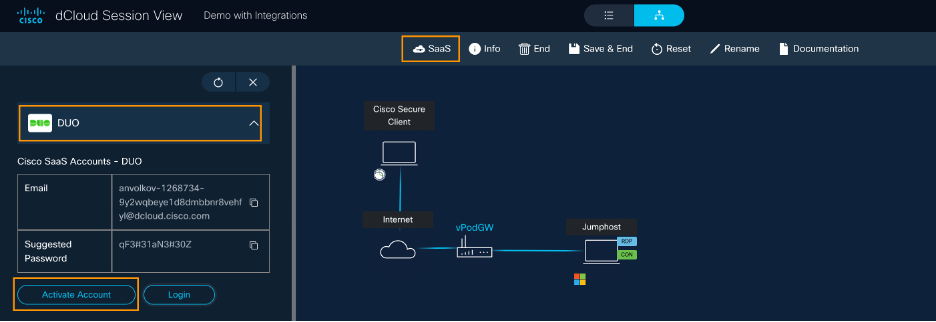
2a. From the dCloud session view, click Activate Account, set your password, and configure the multi-factor authentication (MFA). using the DUO mobile app.
Note: Some steps in the screenshots below are omitted for brevity.
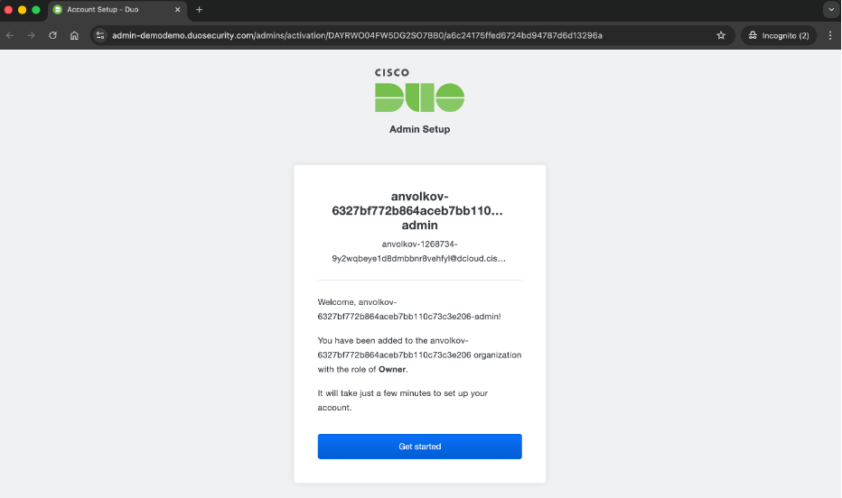
2b. For the MFA setup, use the DUO application installed on your mobile phone.
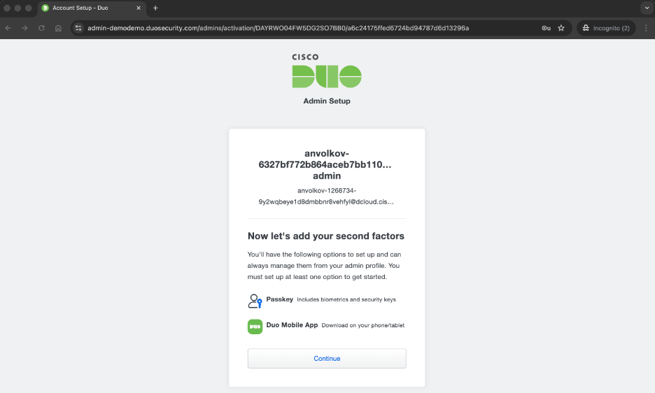
2c. When your DUO account is activated, you can access it from the dCloud Session View > SaaS tab by clicking the Login button.
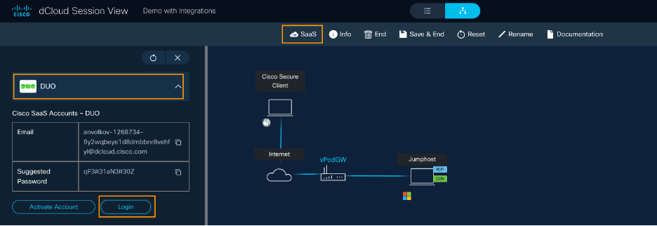
2d. To log in, use the provided email address and the password, and complete the MFA as prompted.
Drive Customer Business Value with Cisco Secure Endpoint Integration
Cisco Secure Endpoint offers advanced endpoint protection by detecting, blocking, and responding to threats in real time, helping safeguard your devices and data from malware and attacks. Integrating Cisco Secure Endpoint into your topology can help your customers:
- Protect endpoints with advanced threat detection and response capabilities integrated into your security ecosystem.
- Automate endpoint security workflows to reduce manual effort and improve incident response times.
- Gain unified visibility across endpoint devices to detect and remediate threats before they impact business operations.
- Enhance compliance posture by enforcing endpoint security policies consistently across the environment.
Configure Cisco Secure Endpoint (AMP) Integration
When using Cisco Secure Endpoint (previously known as Cisco AMP) Integration in your topology, a new Cisco Secure Endpoint account will be created.
Cisco Secure Endpoint Integration does not have any custom parameters for you to configure.
1. Open the Edit SaaS Integration page for AMP.
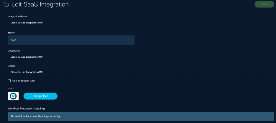
2. In Session View, expand AMP in the SaaS tab.
3. Cick Go to Account to log in.
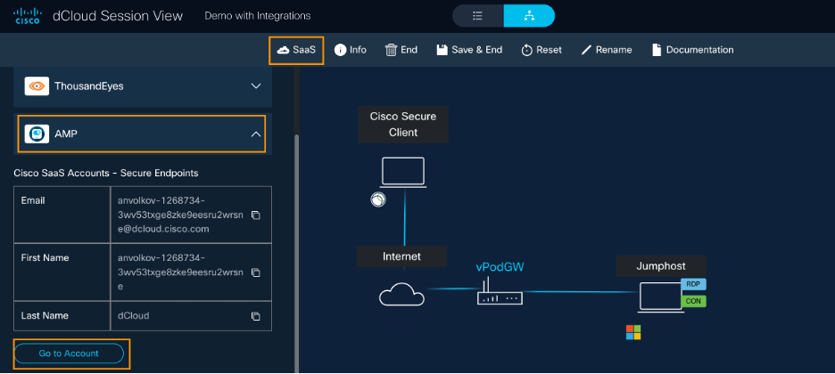
If you experience any login issues, try using a Private (or Incognito) browser window.
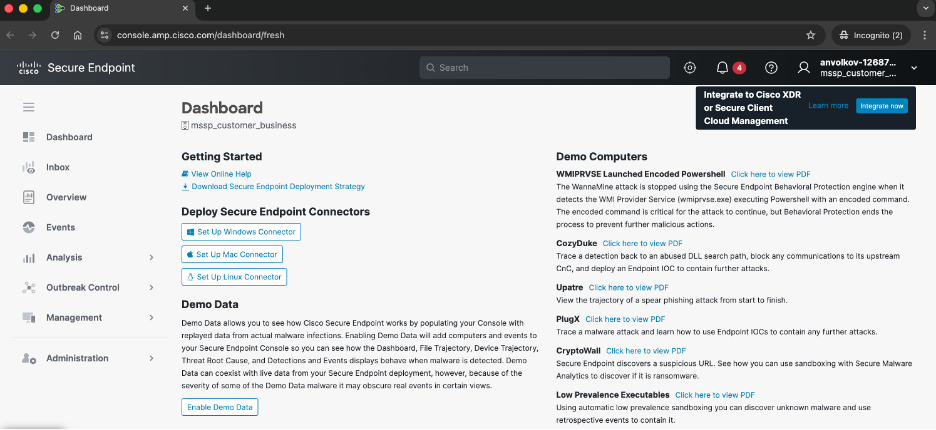
Drive Business Value with Umbrella Integration
Cisco Umbrella provides cloud-delivered security that protects users from internet threats by enforcing security policies and blocking malicious domains before a connection is established. Integrating Umbrella into your topology can help your customers:
- Enhance security posture by blocking malicious domains and IPs before connections are established.
- Utilize centralized policy management to enforce security policies across all users and devices, regardless of location.
- Gain actionable threat intelligence to proactively protect customer environments and reduce risk exposure.
- Simplify security operations by integrating Umbrella data into your existing security workflows and dashboards.
Configure Umbrella Integration
When integrating Umbrella into your topology, a pre-created Umbrella Organization will be assigned to your dCloud session, and the admin account auto-login is generated. When the dCloud session is over, all user-provided configuration will be deleted and Umbrella organization will be returned to the shared resource pool.
Important: For large-scale demos with multiple simultaneous sessions, consider custom resource pools or integrations to ensure sufficient Umbrella accounts.
Cisco Umbrella Integration does not have any custom parameters for you to configure.
1. Open the Edit SaaS Integration page for Cisco Umbrella.
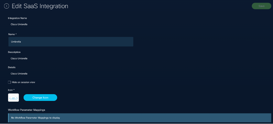
2. Under dCloud Session View, expand Umbrella in the SaaS tab.
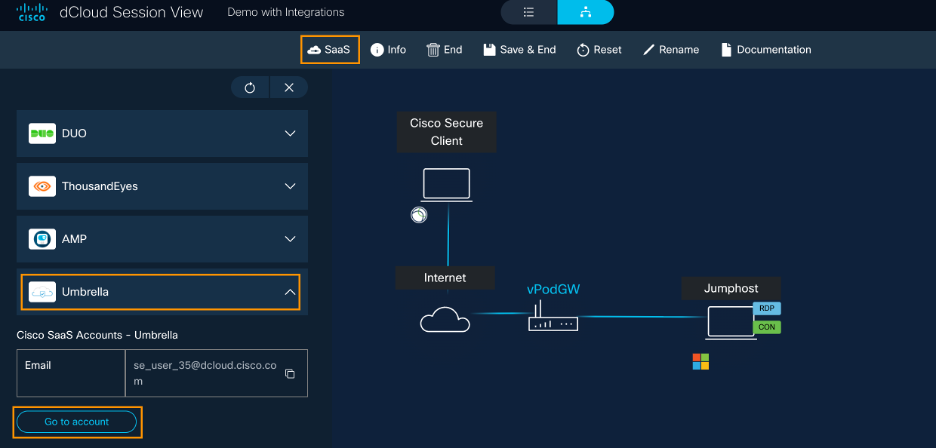
3. Click the Go to Account button to log in to the Cisco Umbrella Admin portal.
If you experience any login issues, try using a Private (or Incognito) browser window.
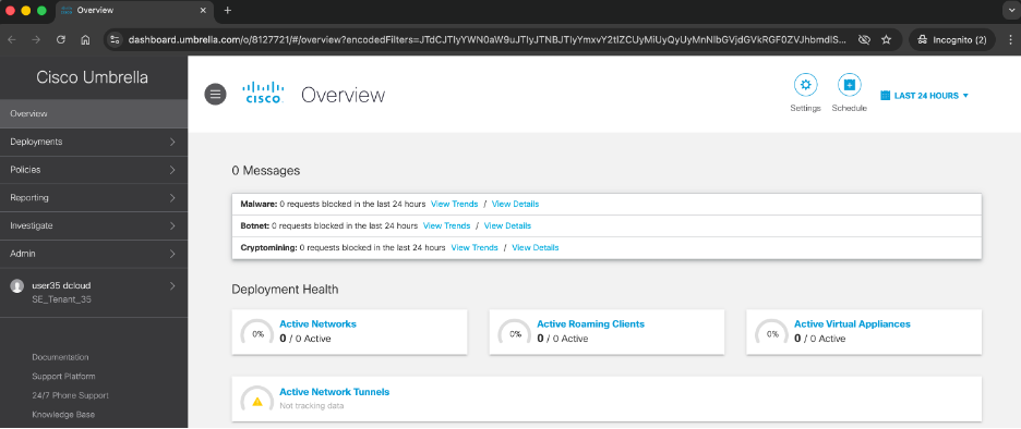
Continuous improvement: Your feedback matters
We are committed to a world-class partner experience. Your feedback drives our roadmap.
- Encountered a challenge? Click the blue "Give Feedback" banner on the right of the page.
- Have a success story? Share how Cisco eXpo! helped drive a "One Cisco" conversation.

